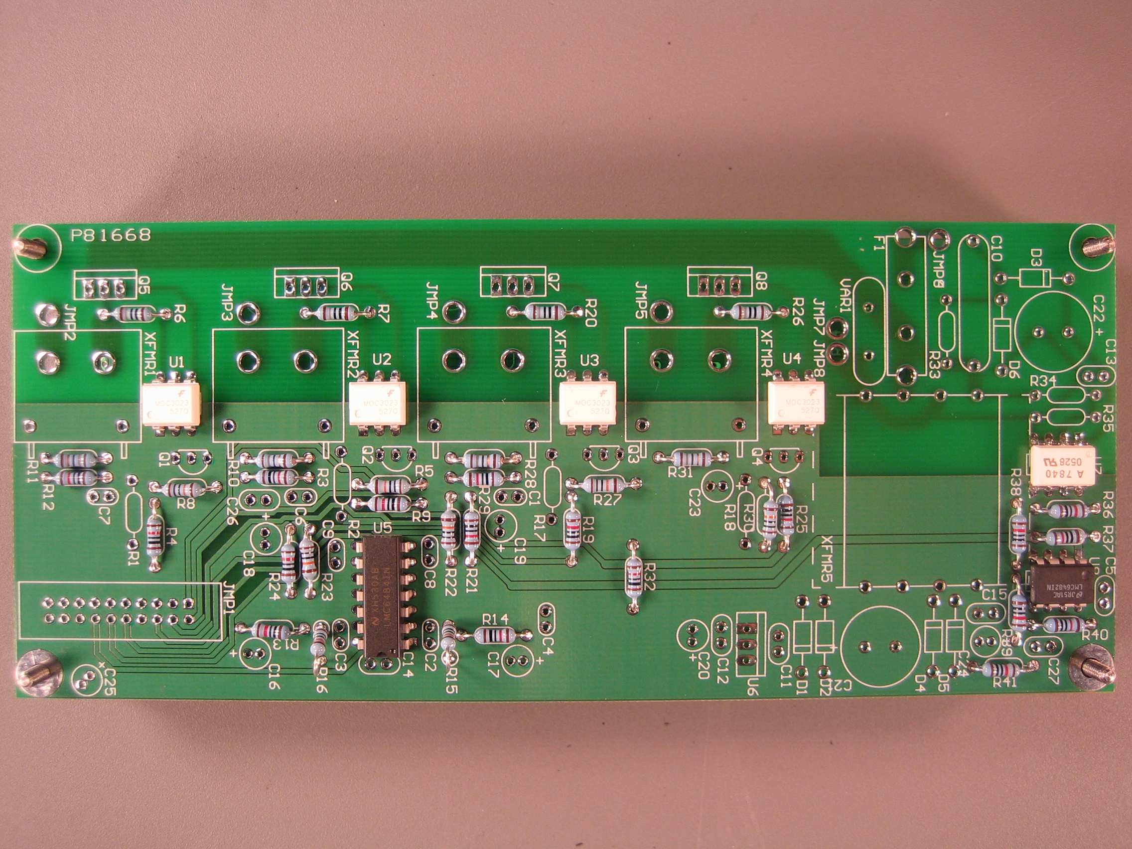
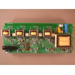
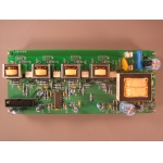
| This guide illustrates how to put together a high
voltage board for the Plug, except for some parts having to do with
the electrical cord. These parts will be added later. |
| Plug High Voltage
Board Schematic [PDF]. |
| COMPONENT | PLACEMENT |
DESCRIPTION (parity matters if text is highlighted yellow)
|
|
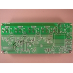 |
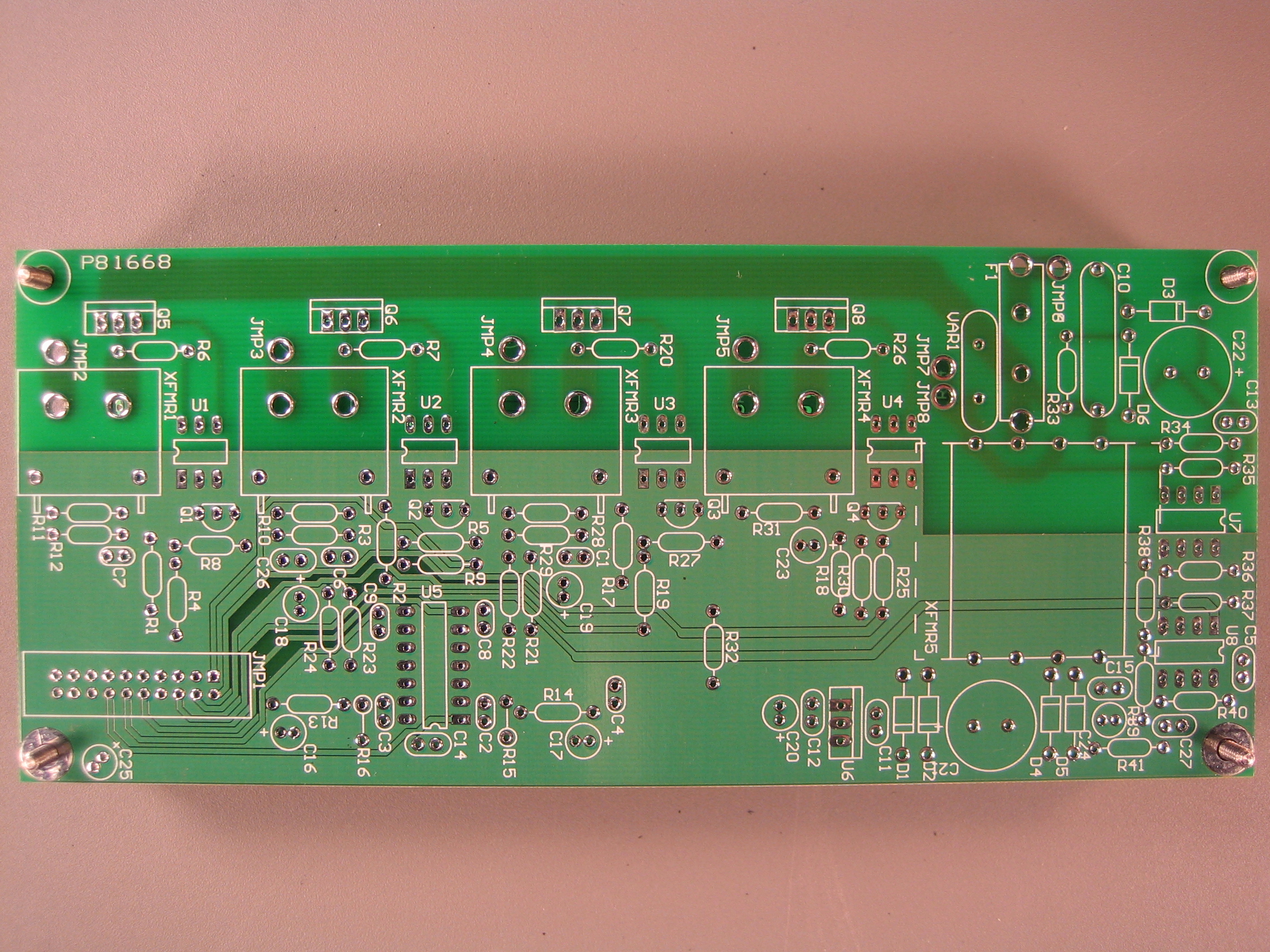
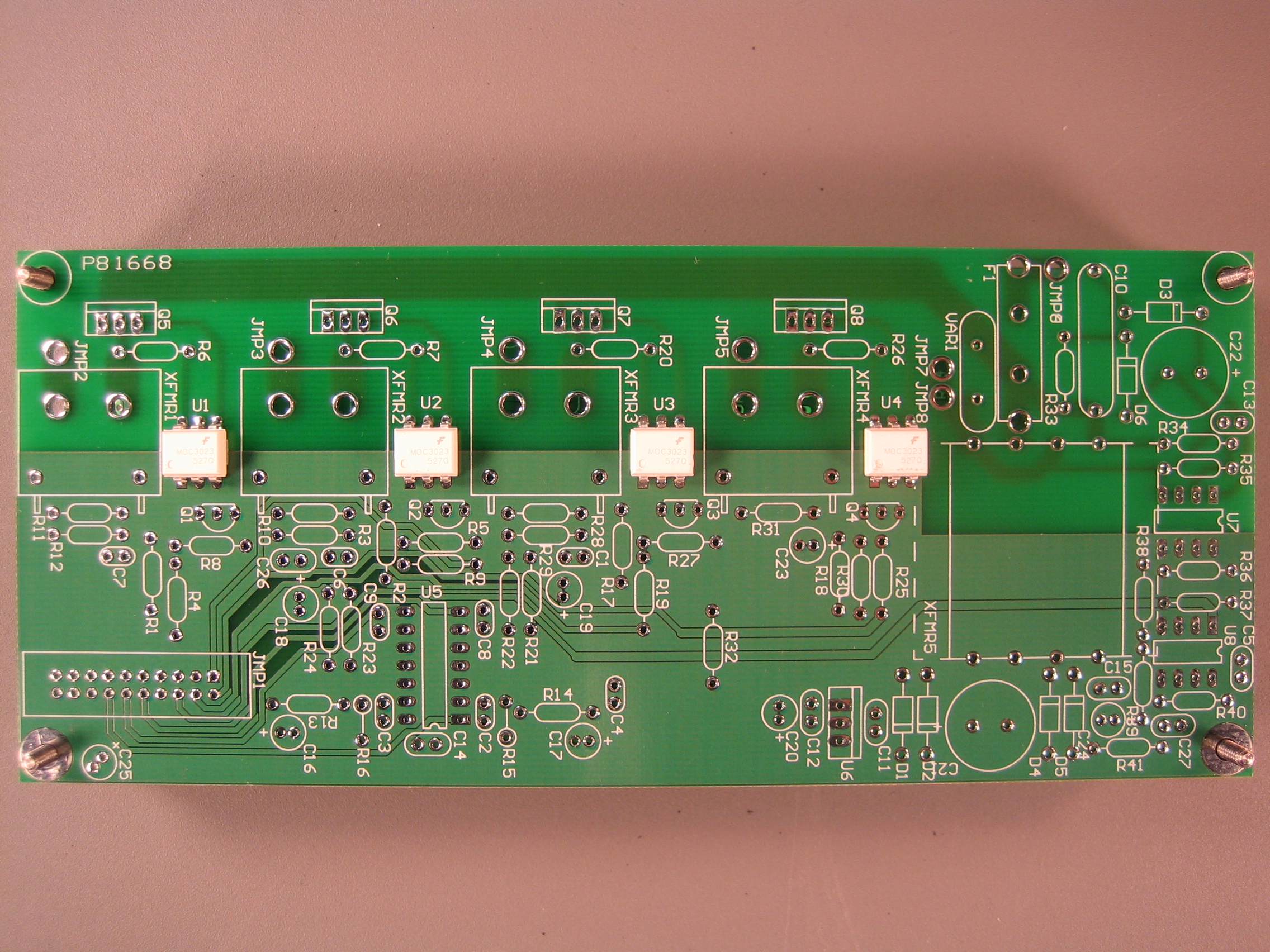
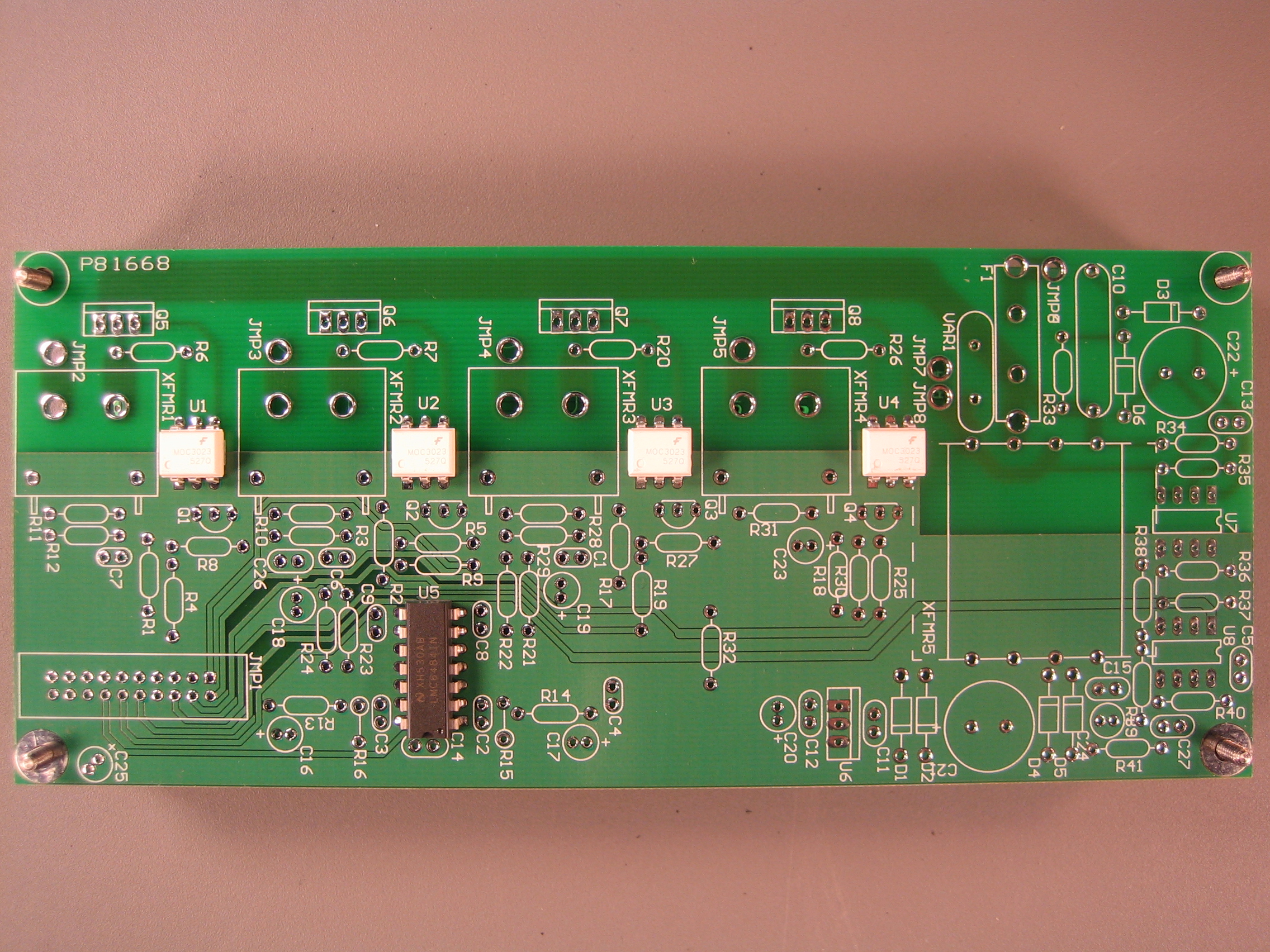
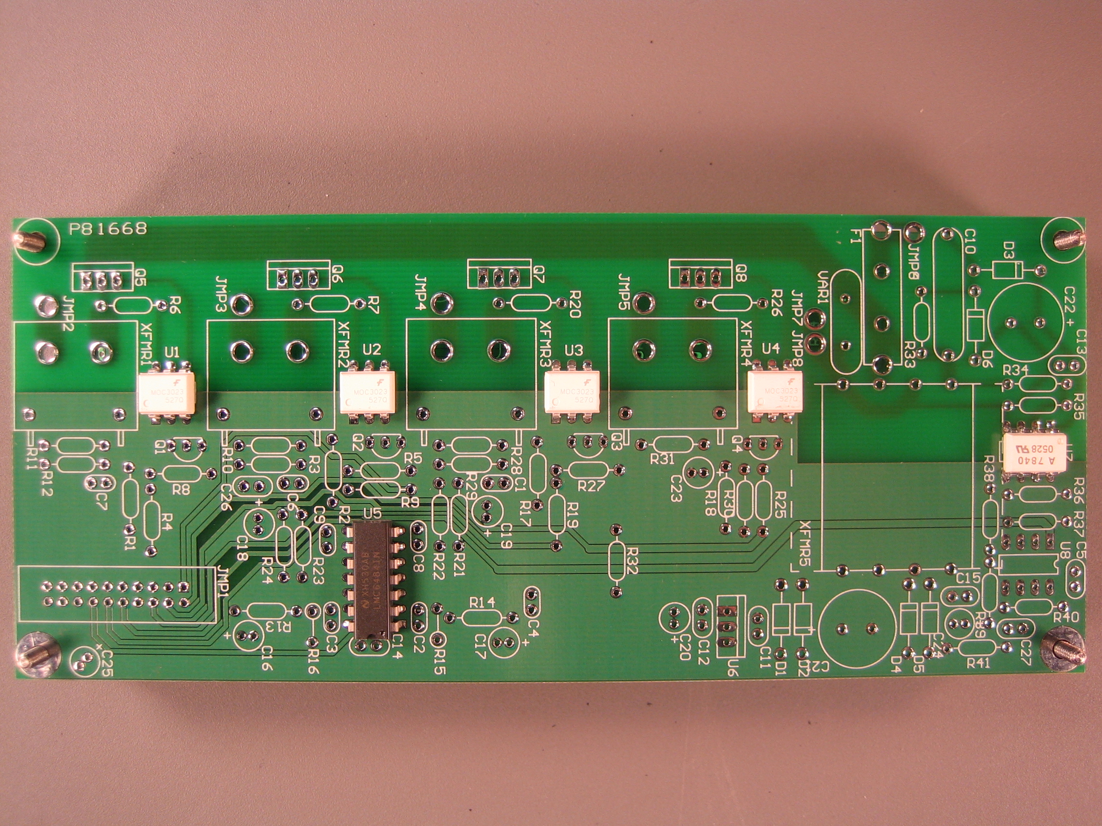
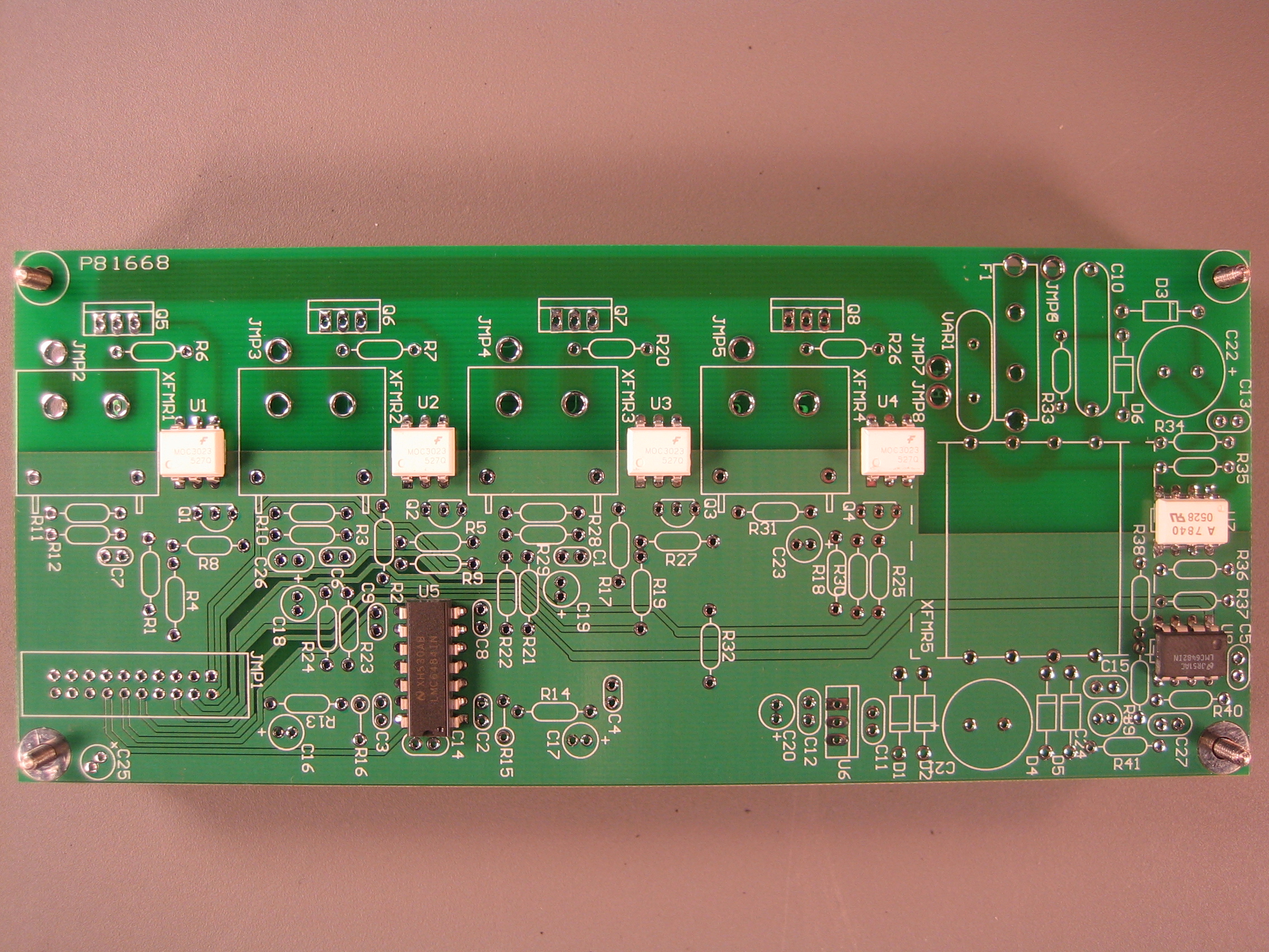
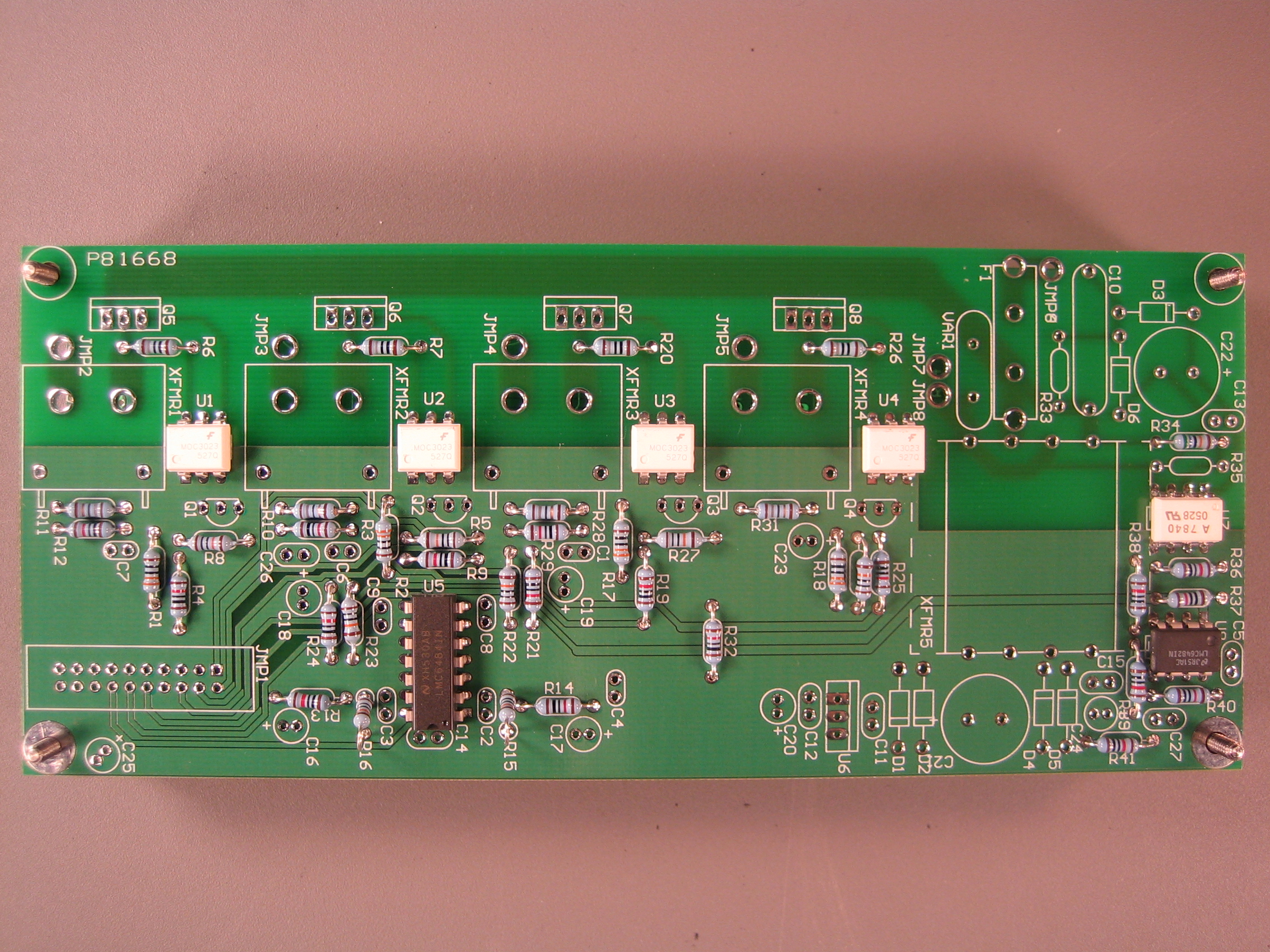
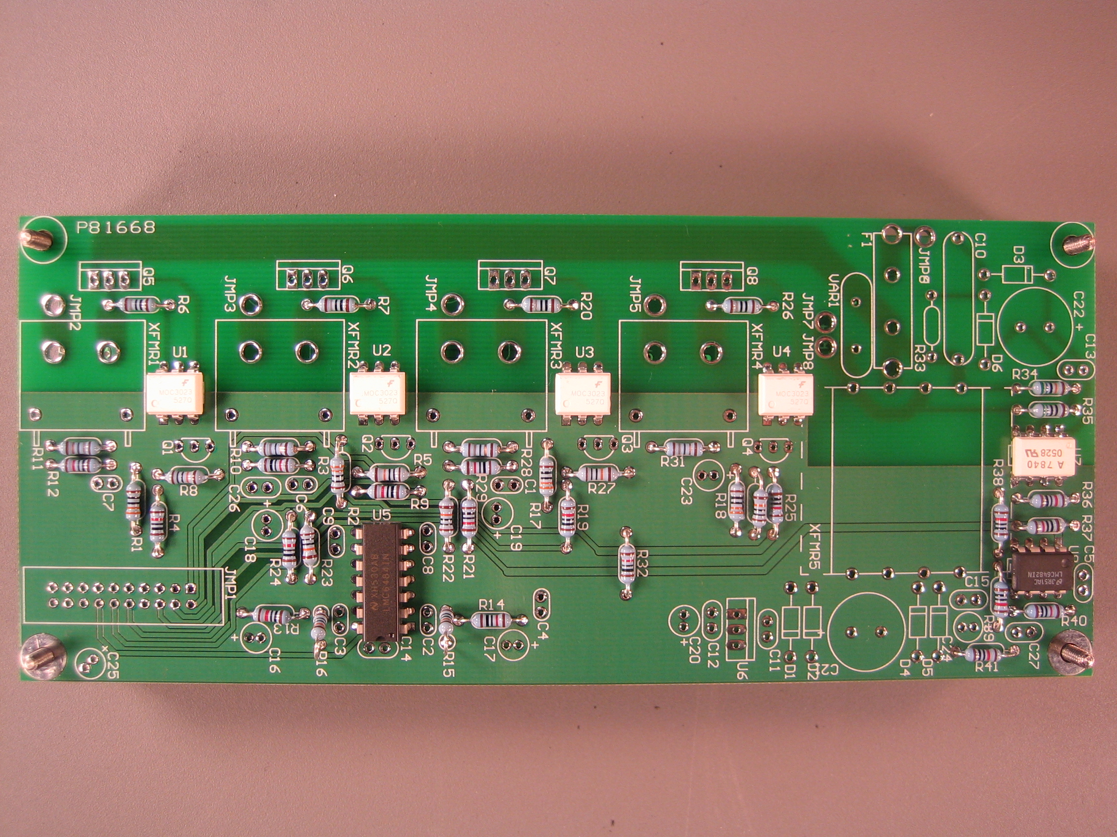
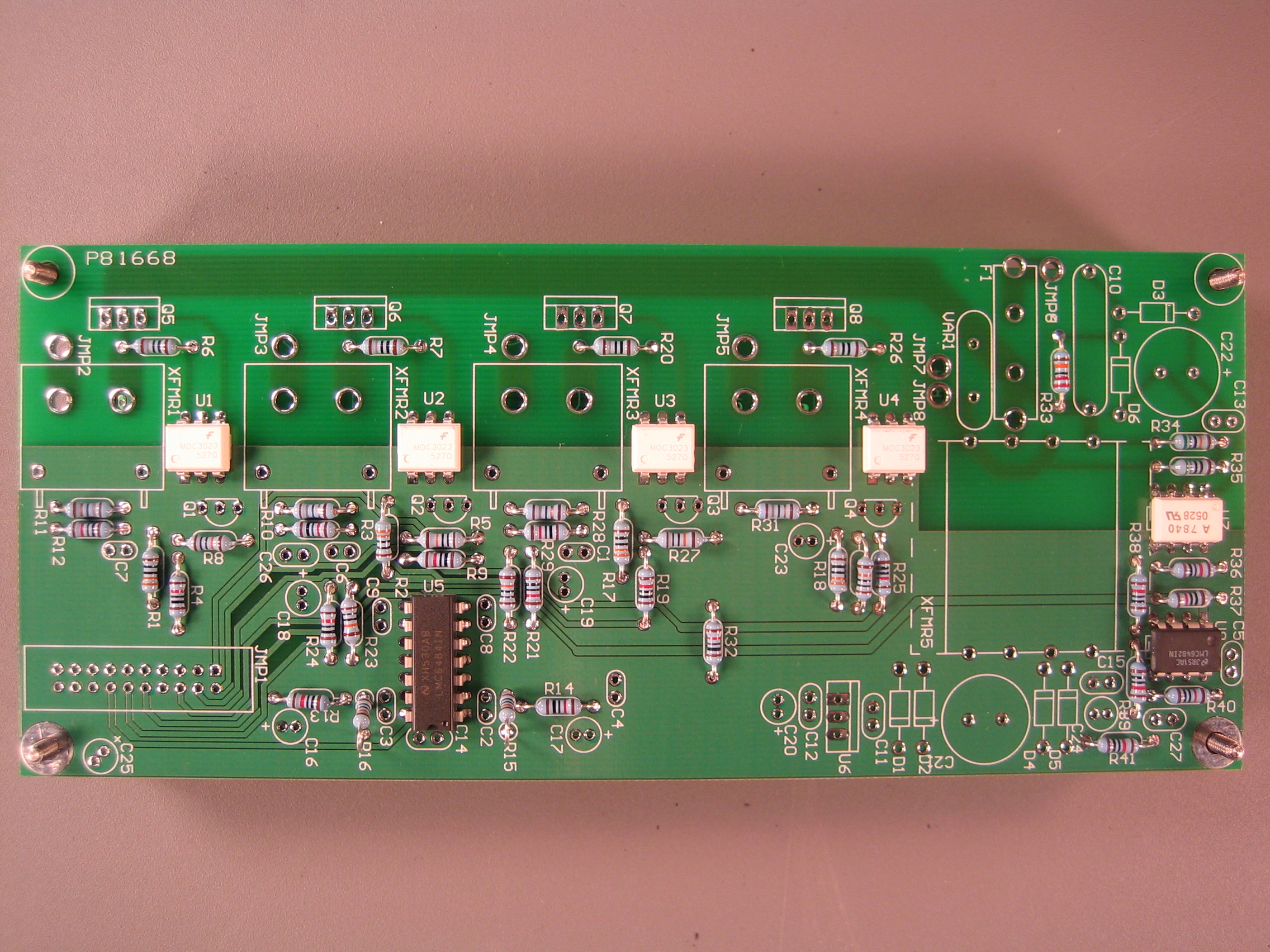
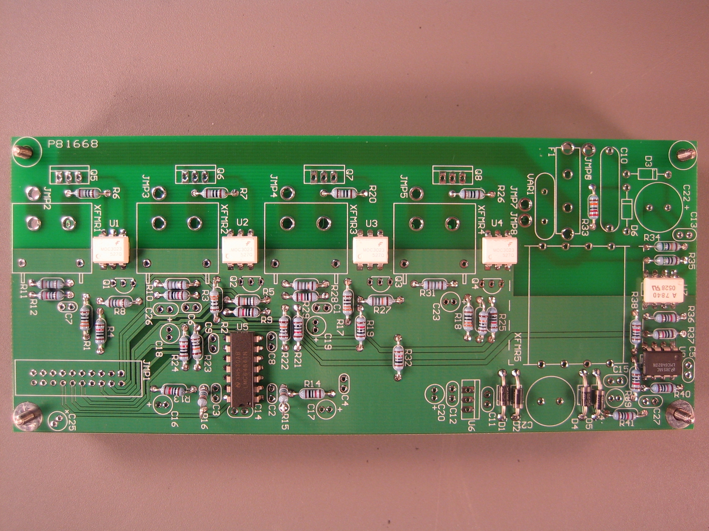
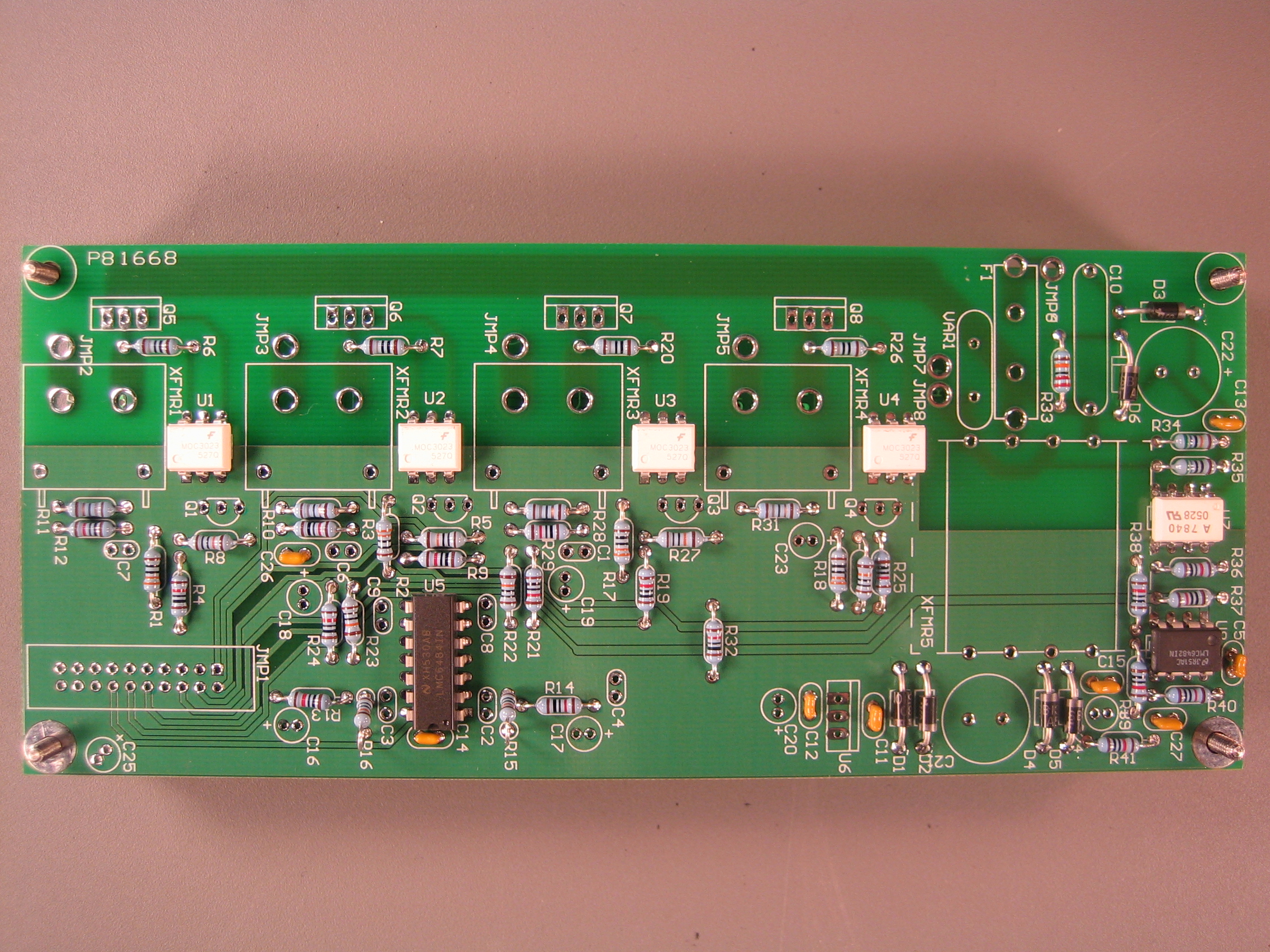
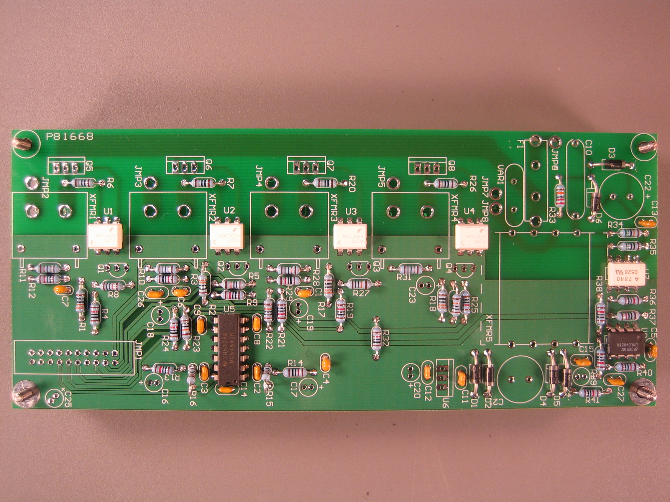
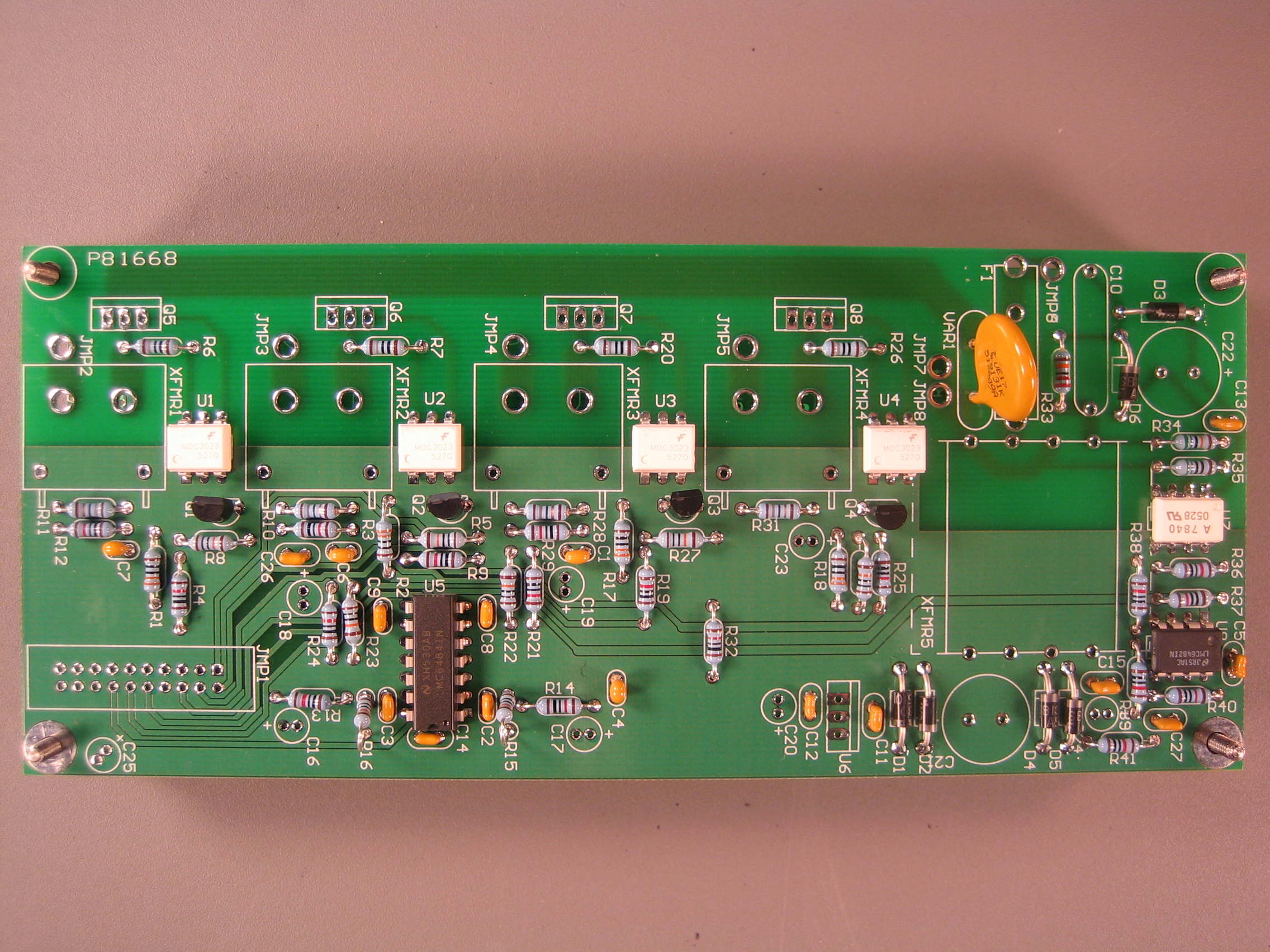
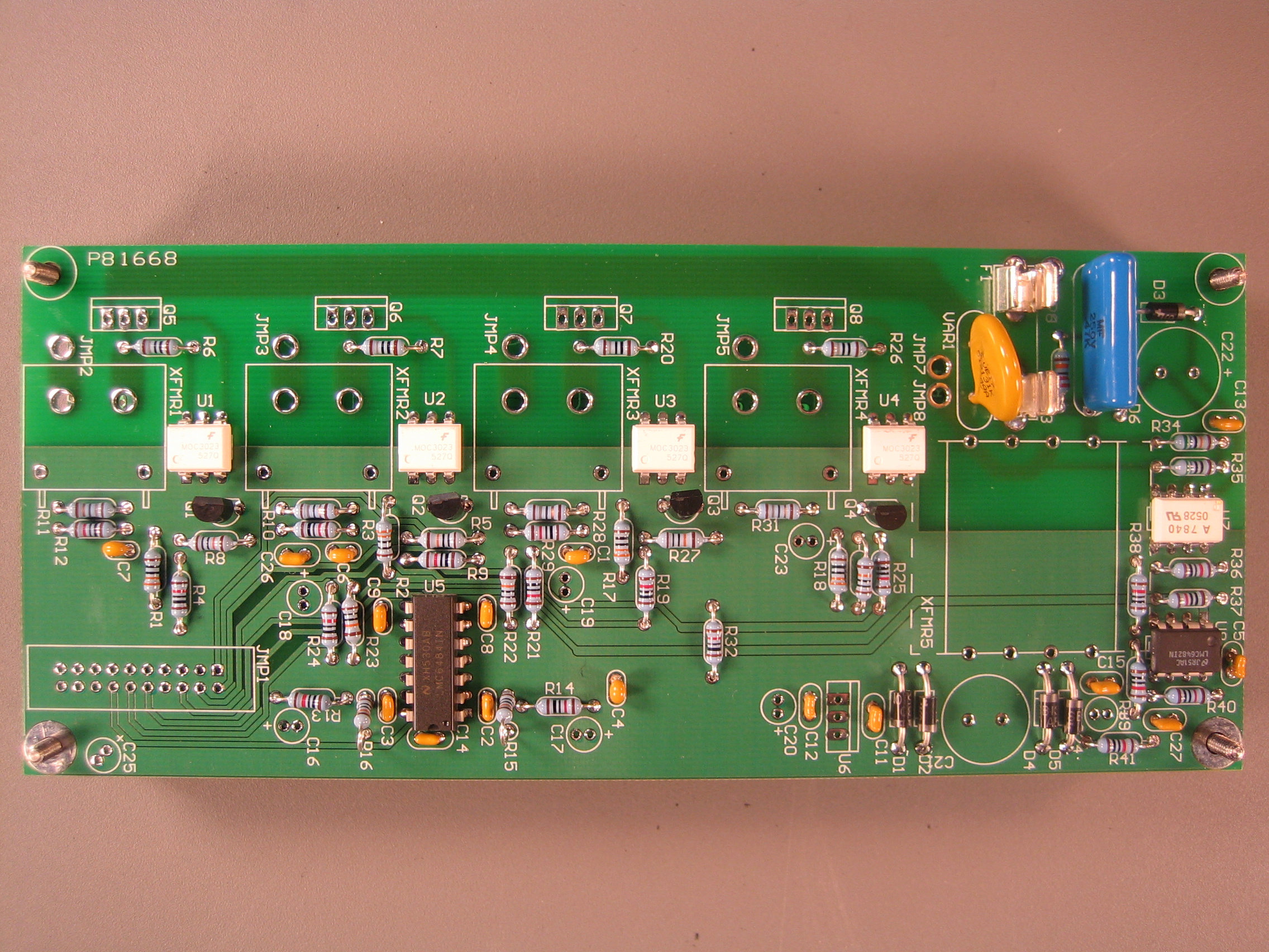
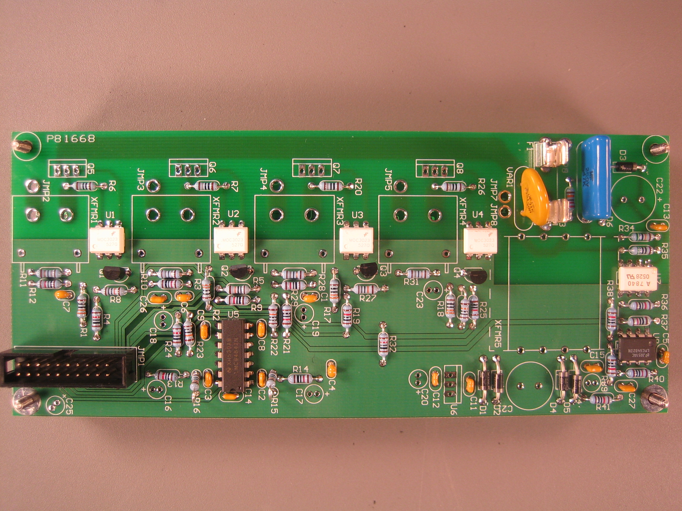
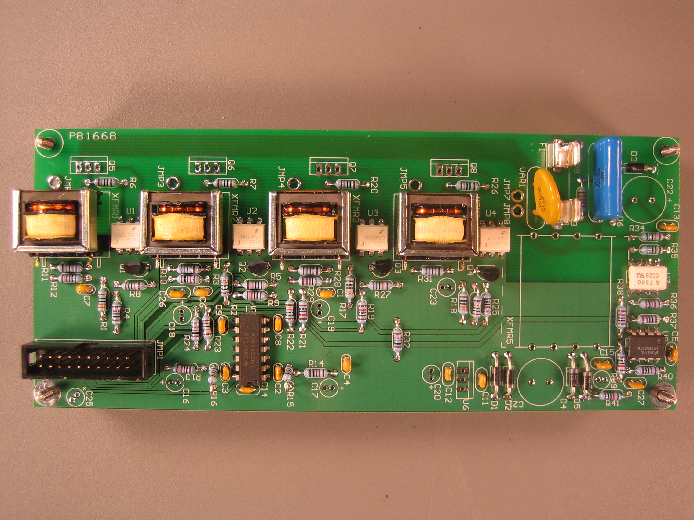
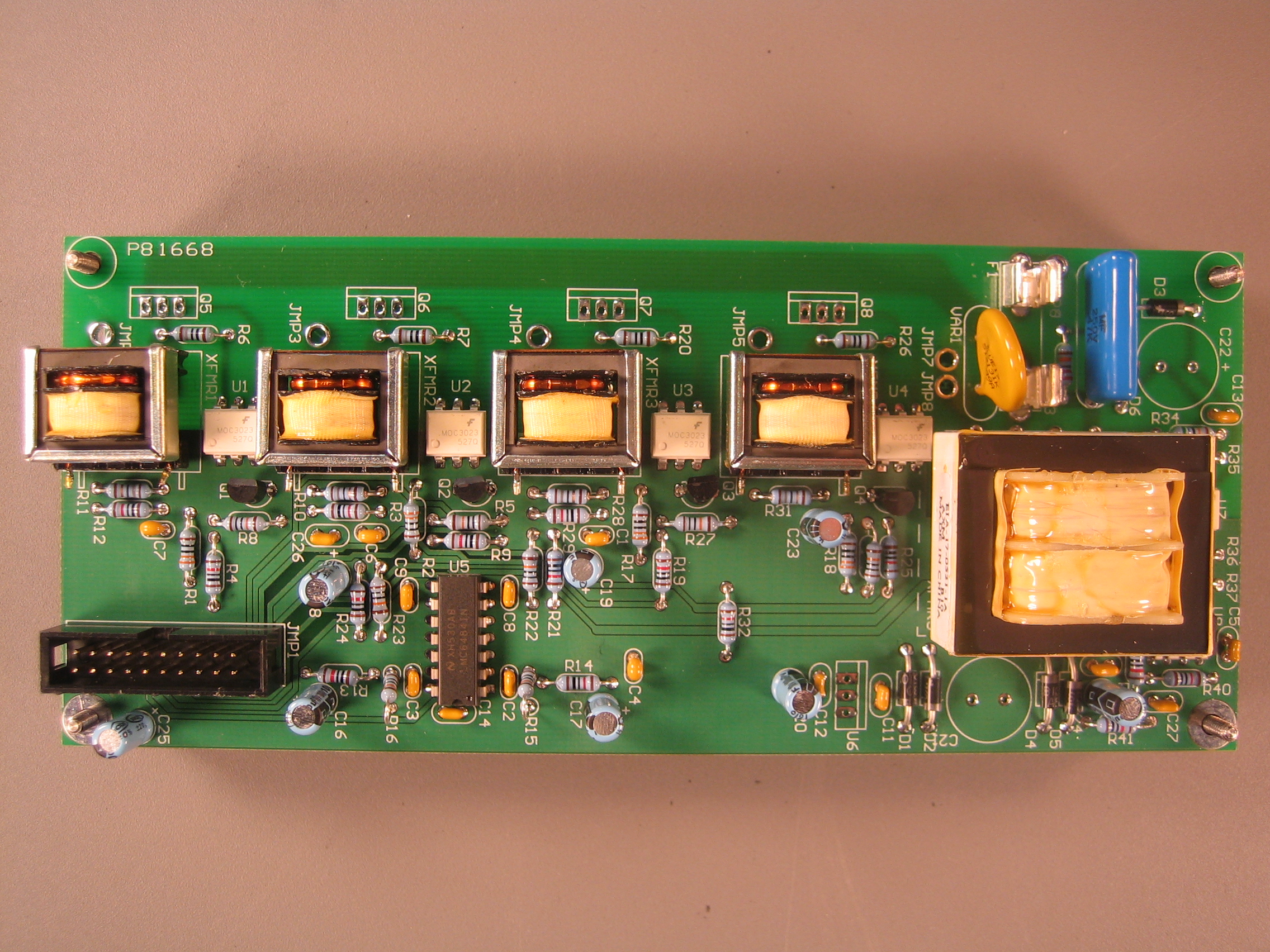
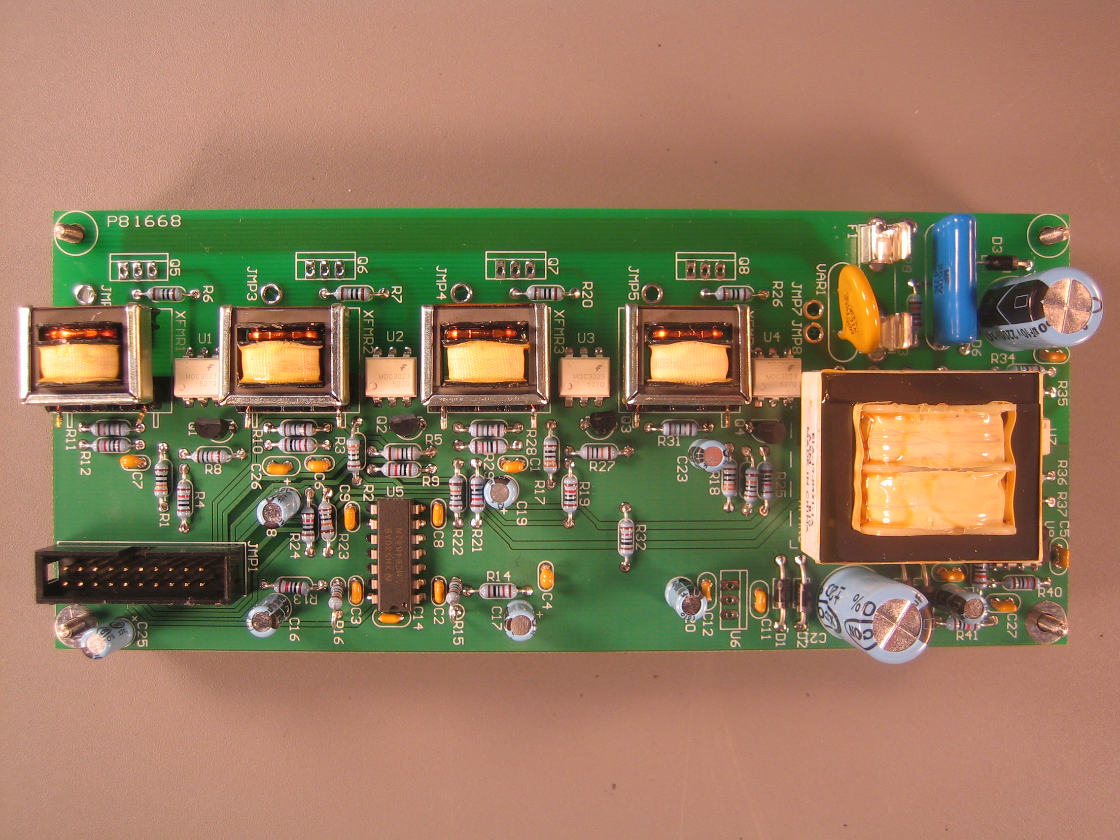
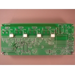
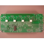
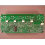
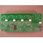
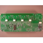
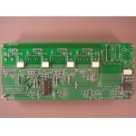
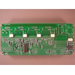
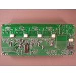
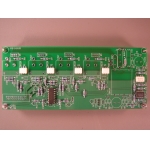
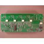
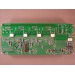
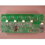
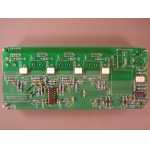
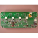
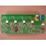
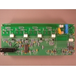
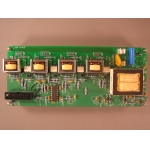
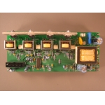
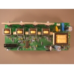
The top side of the plug high voltage printed circuit board before any
components have been added.
|
 |
 |
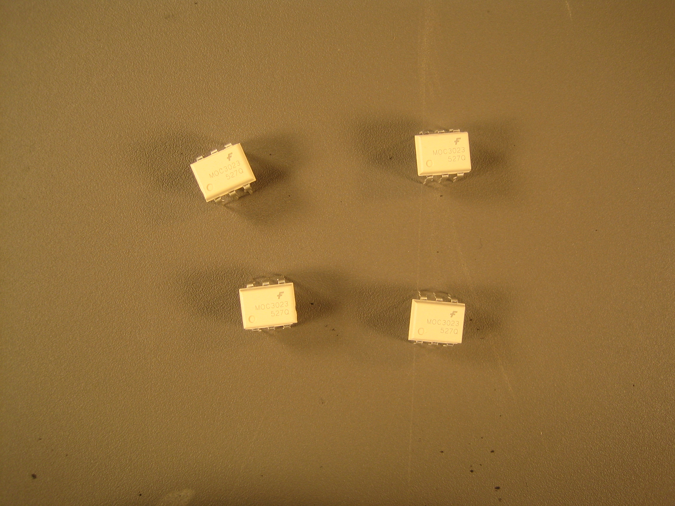
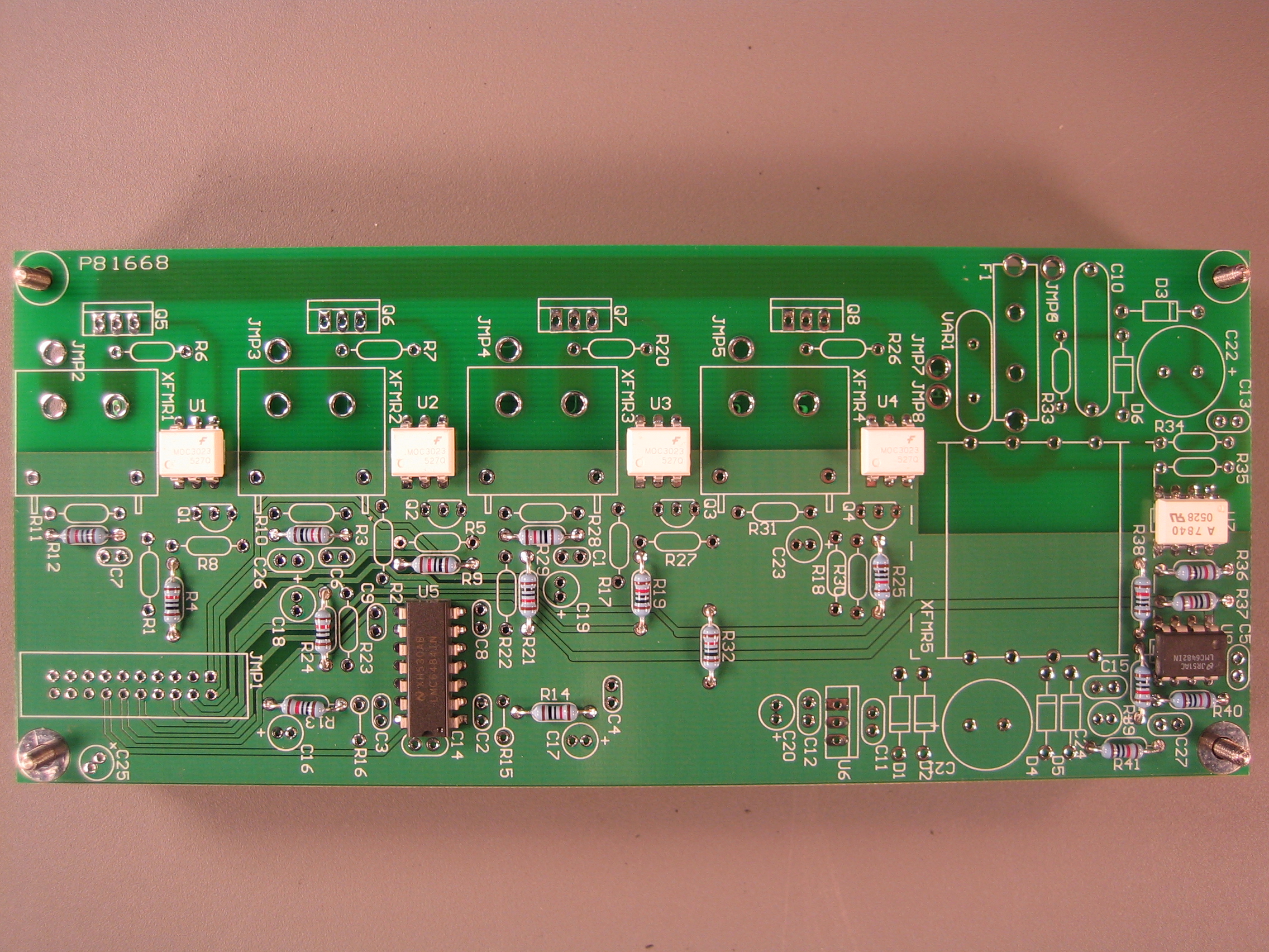
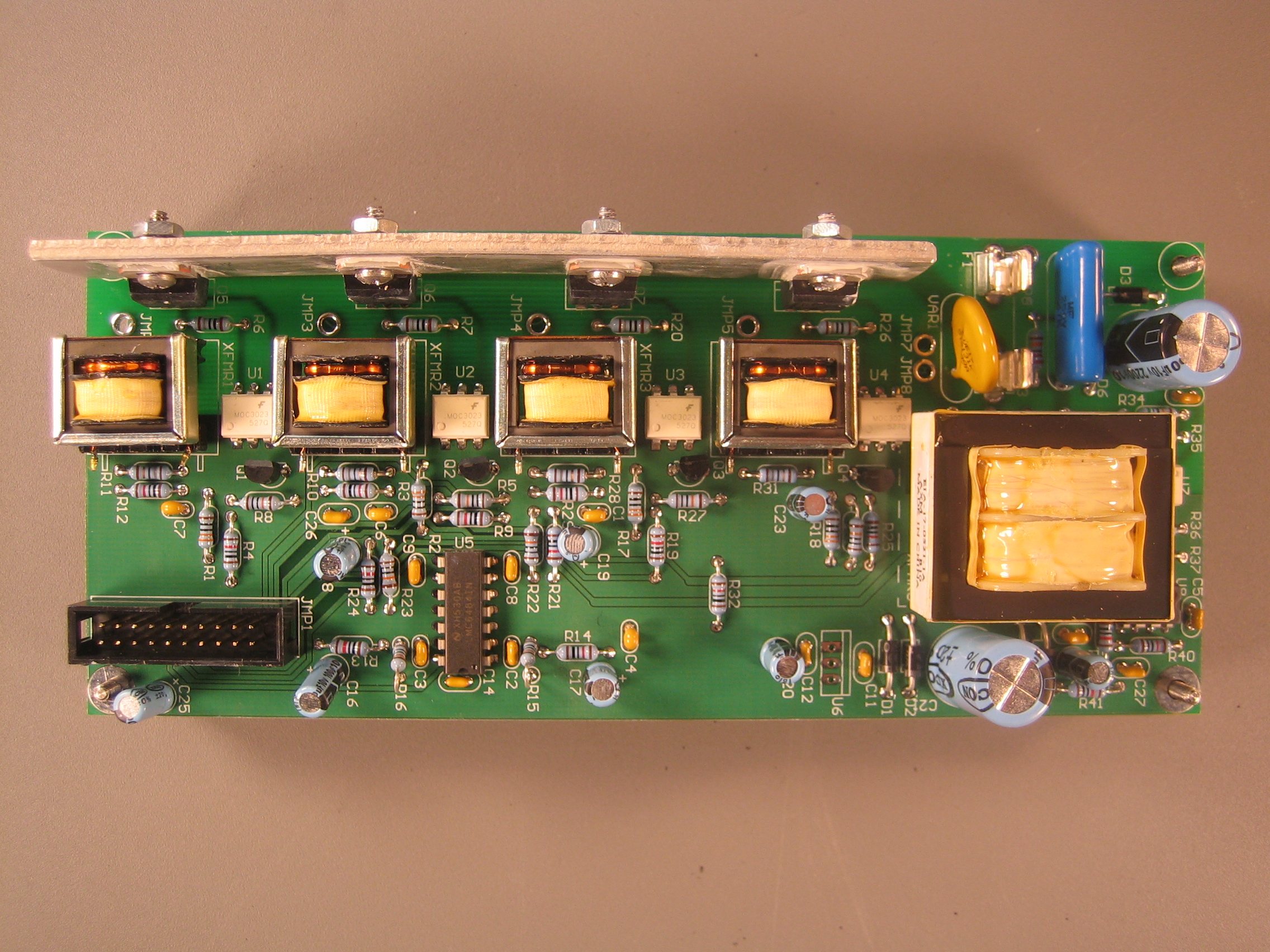
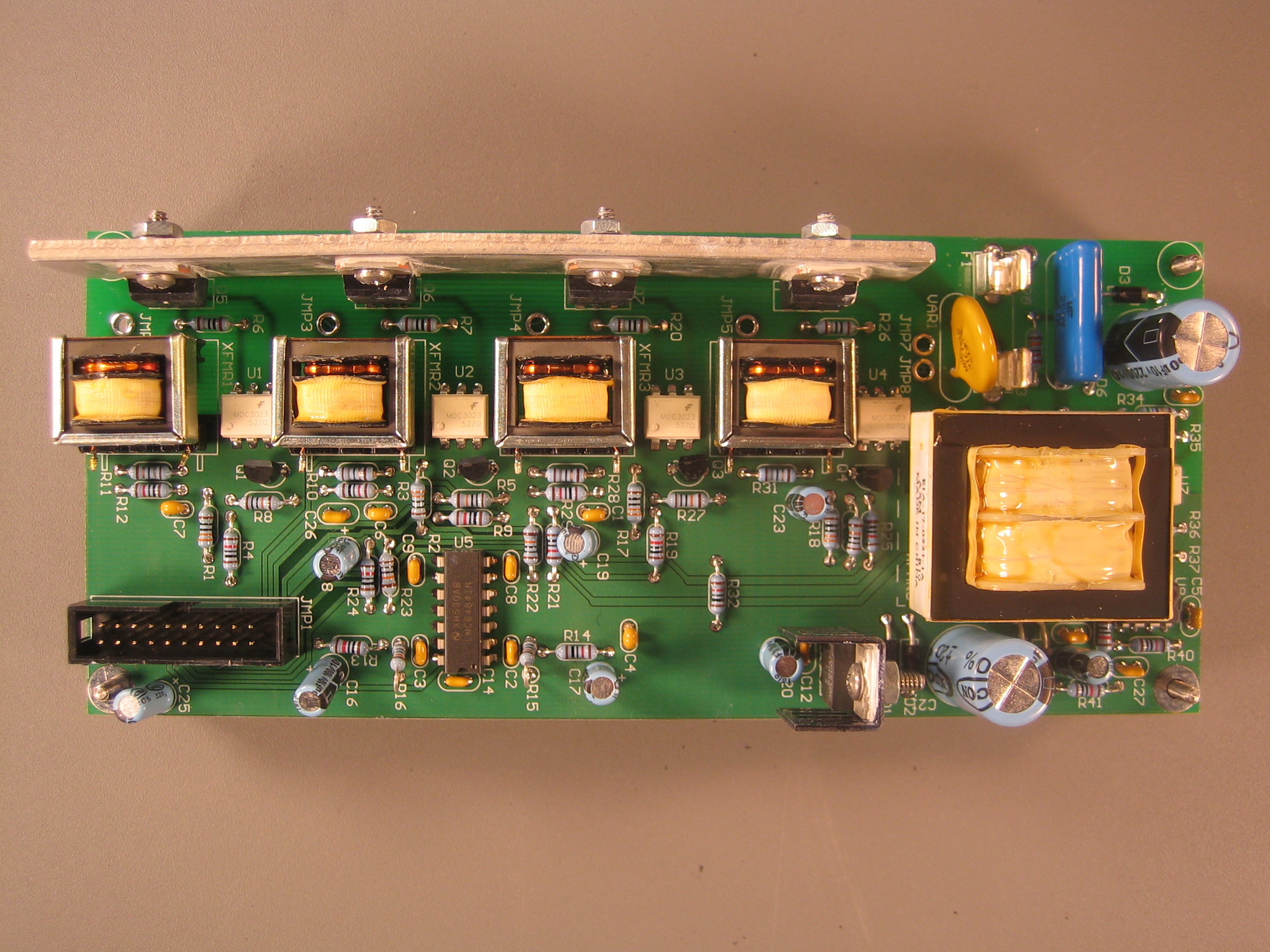
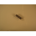
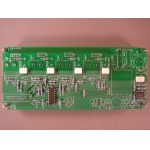
Fairchild Semiconductor MOC3023 6-Pin DIP 400V Random Phase Triac
Driver Output Optocoupler (U1, U2, U3, U4).
|
 |
 |
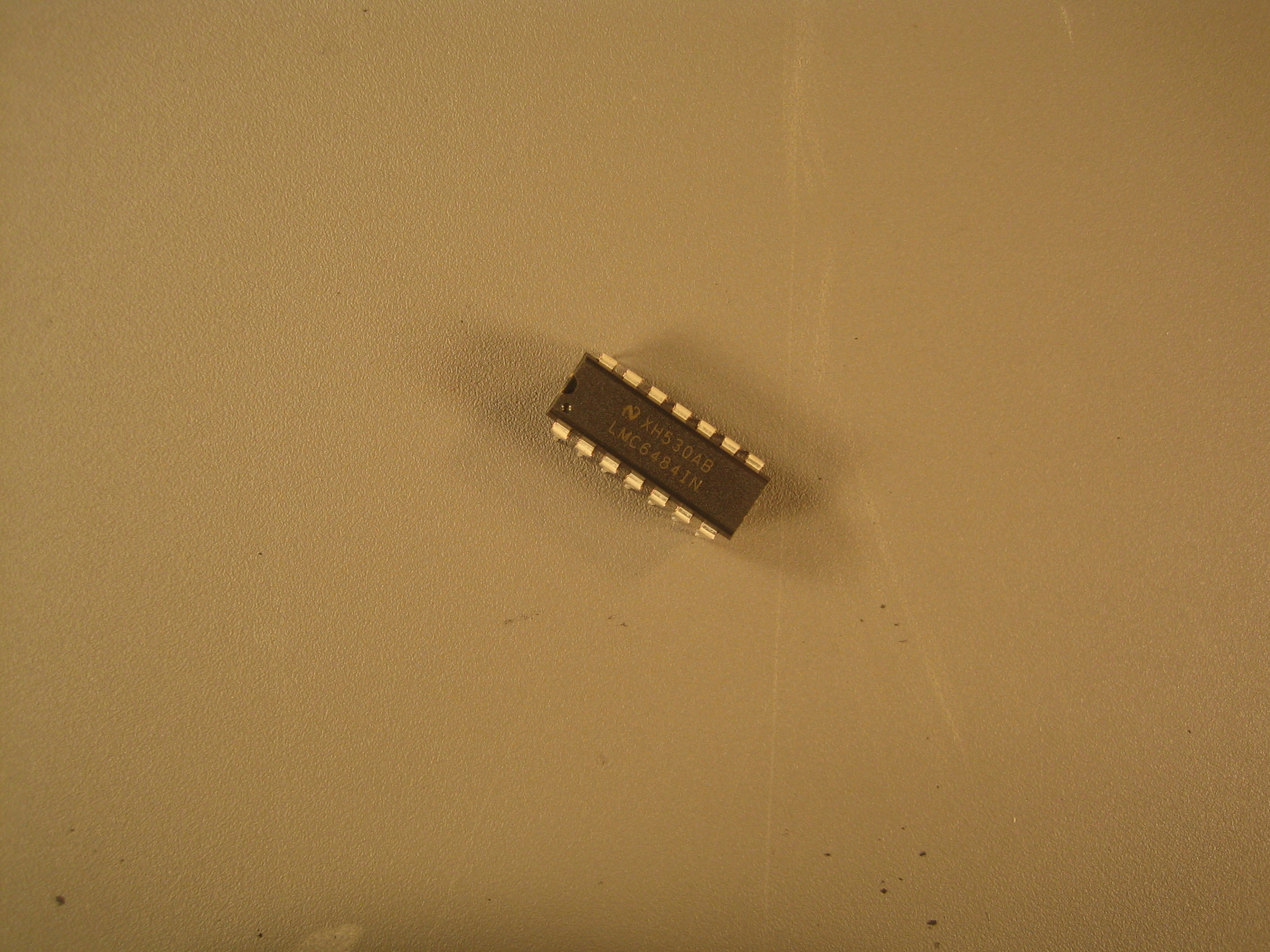
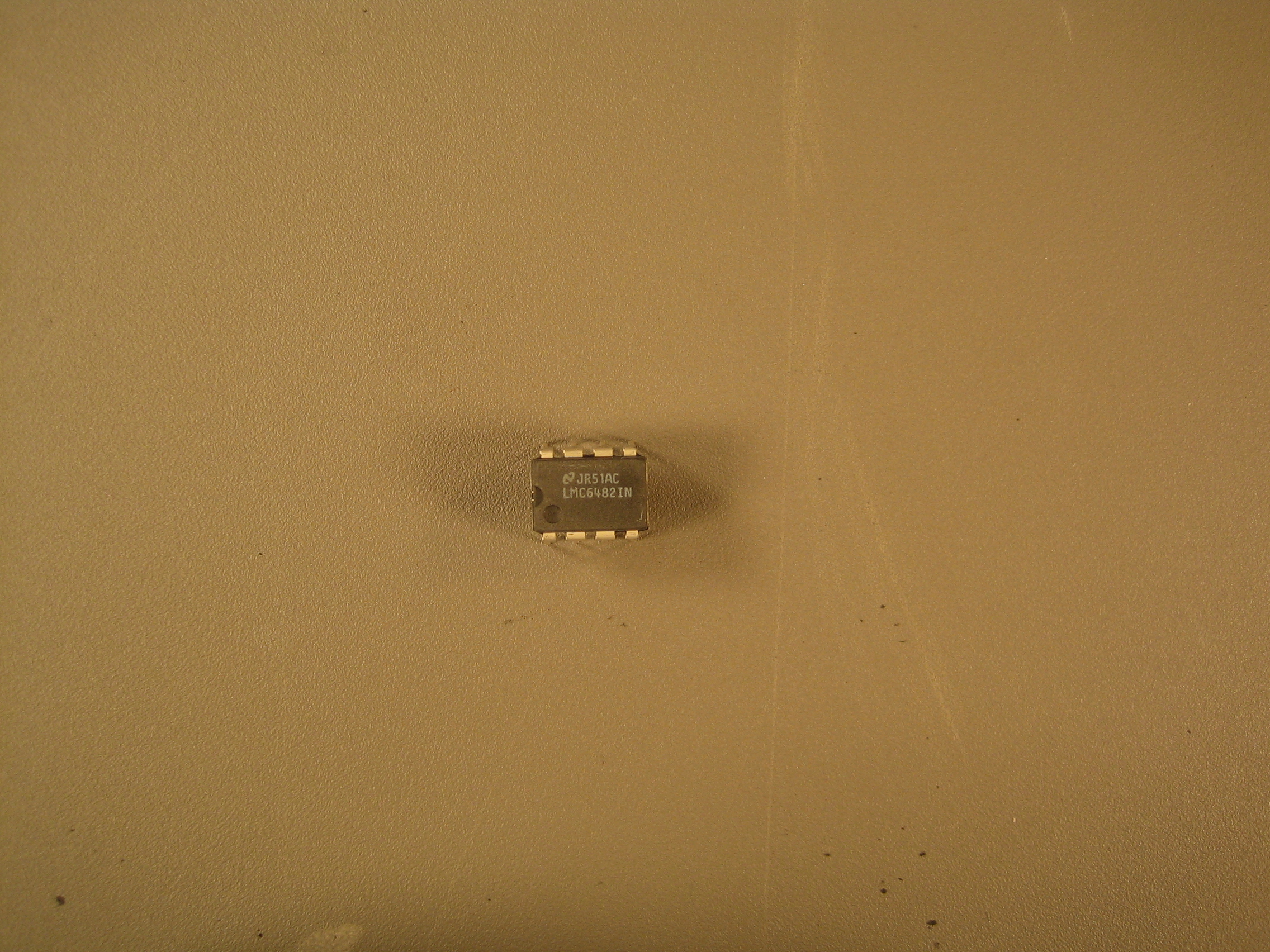
The National Semiconductor LMC6484 CMOS quad rail-to-rail input and
output operational amplifier (U5).
|
 |
 |
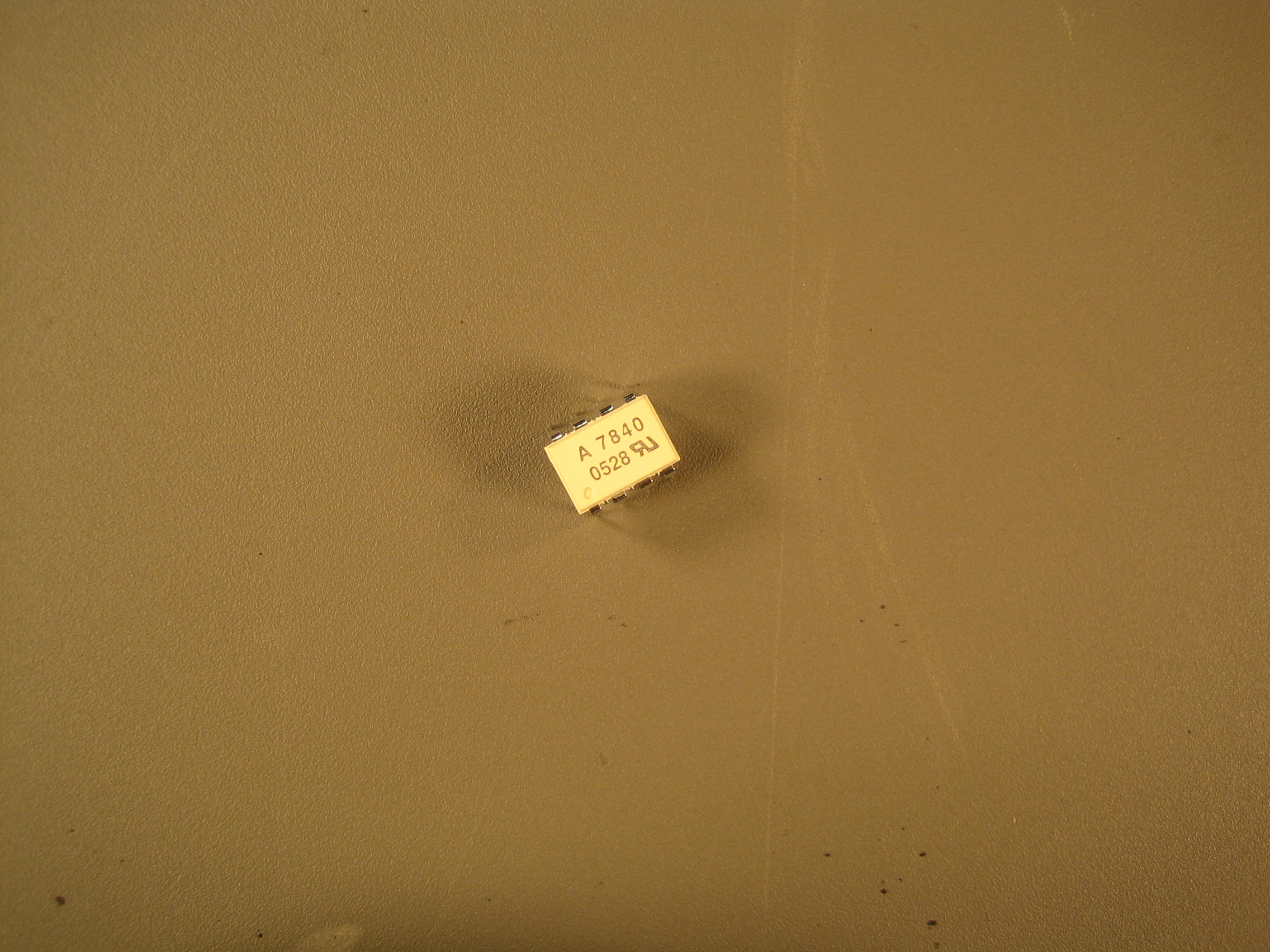
Agilent Technologies HCPL-7840 Isolation Amplifier (U7).
|
 |
 |
National Semiconductor CMOS dual rail-to-rail input and output
operational amplifier (U8).
|
 |
 |
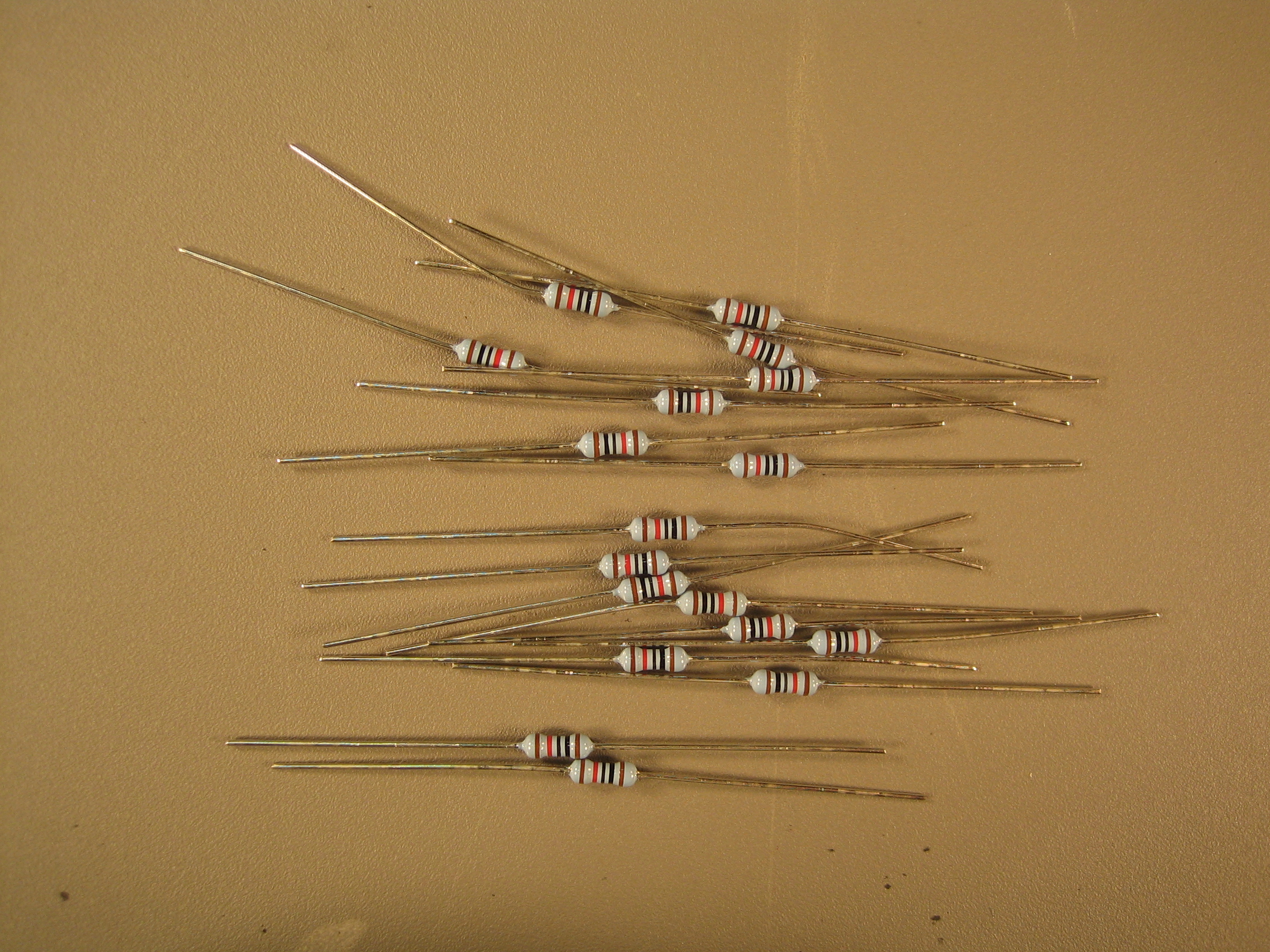
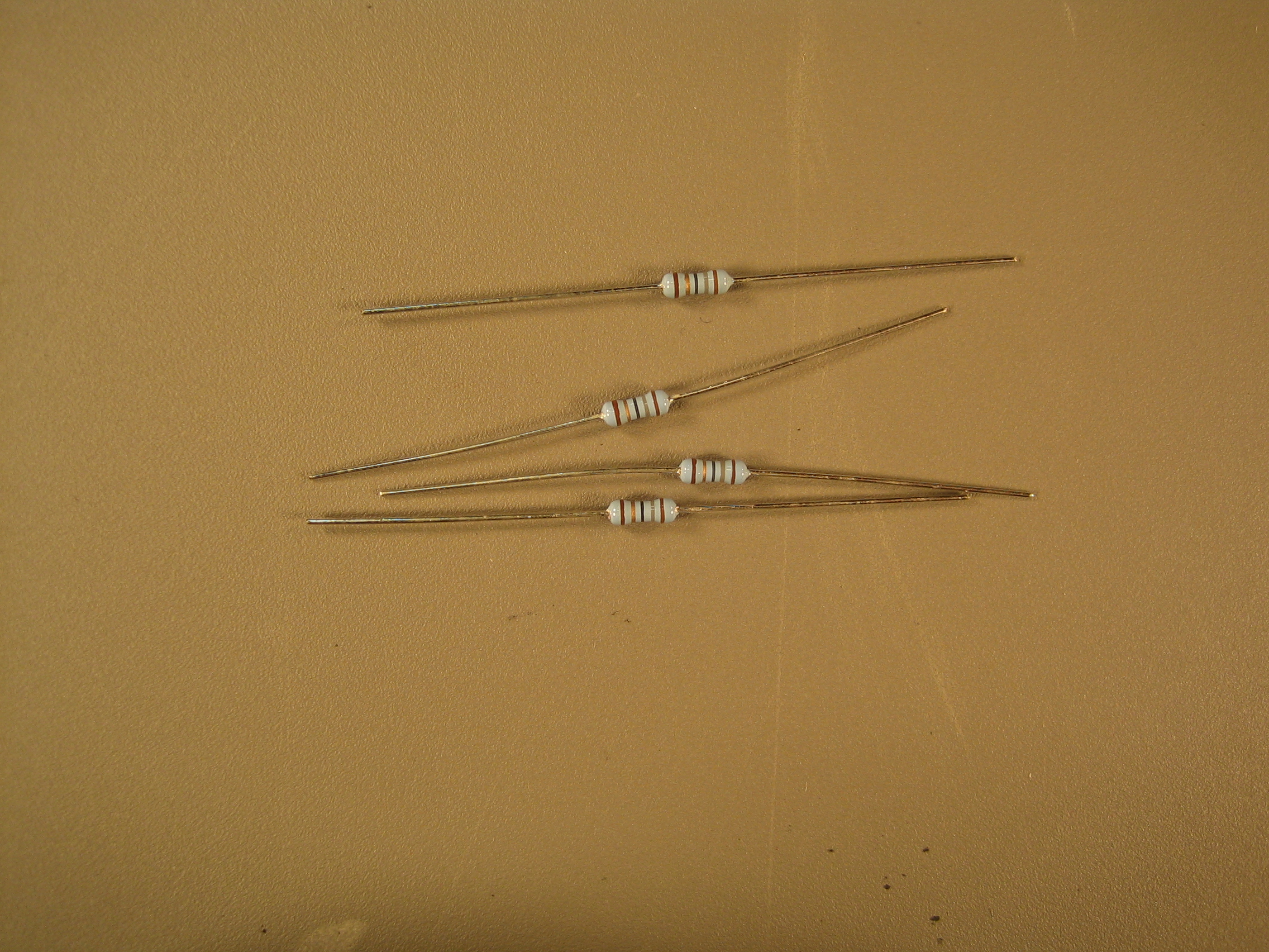
Eighteen 10-kOhm resistors (R3, R4, R5, R12, R13, R14, R19, R21, R24,
R25, R29, R32, R36, R37, R38, R39, R40, R41). WARNING: Two
resistor labels (R5 and R9) are switched on the printed circuit
board. That is, the R5 label should read R9 and the R9 label should
read R5.
|
 |
 |
Eight 100-kOhm resistors (R8, R9, R15, R16, R22, R23, R27, R30).
WARNING: Two resistor labels (R5 and R9) are switched on the
printed circuit board. That is, the R5 label should read R9 and the
R9 label should read R5.
|
 |
 |
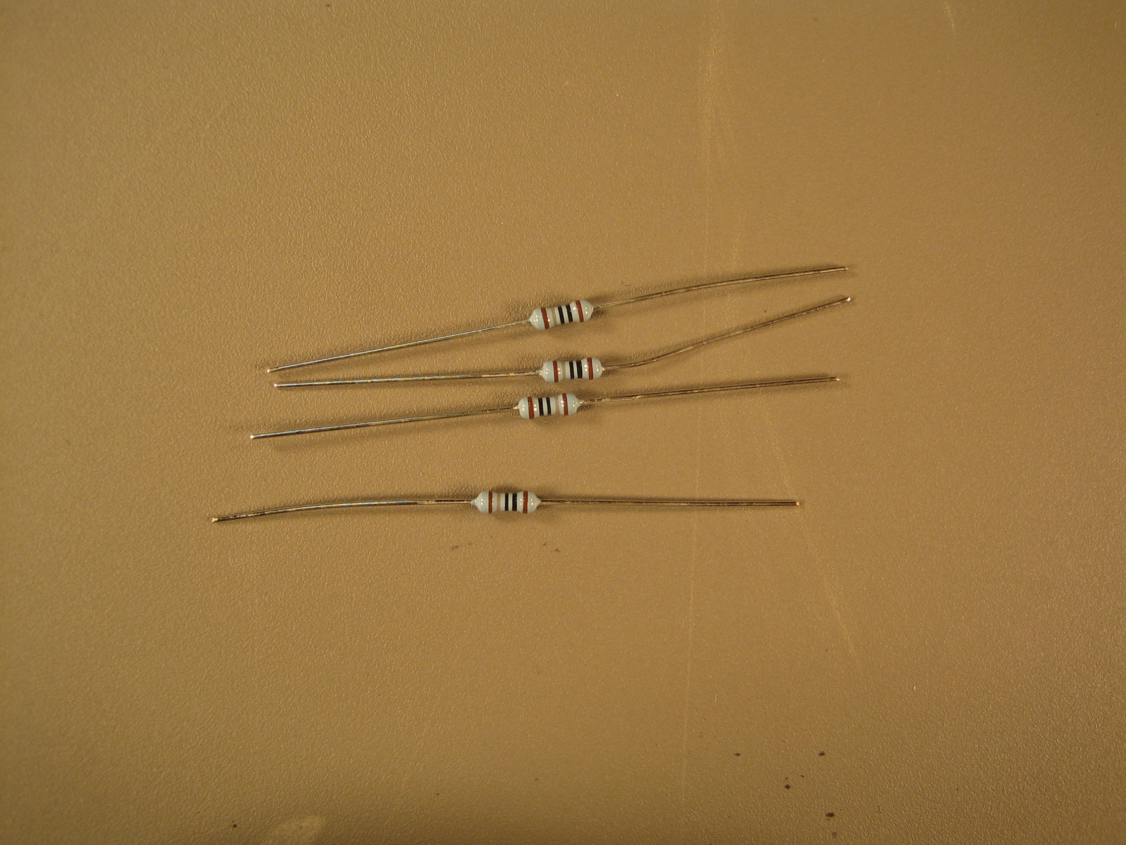
Four 18-Ohm resistors (R10, R11, R28, R31).
|
 |
 |
Four 180-Ohm resistors (R6, R7, R20, R26).
|
 |
 |
Four 330-Ohm resistors (R1, R2, R17, R18).
|
 |
 |
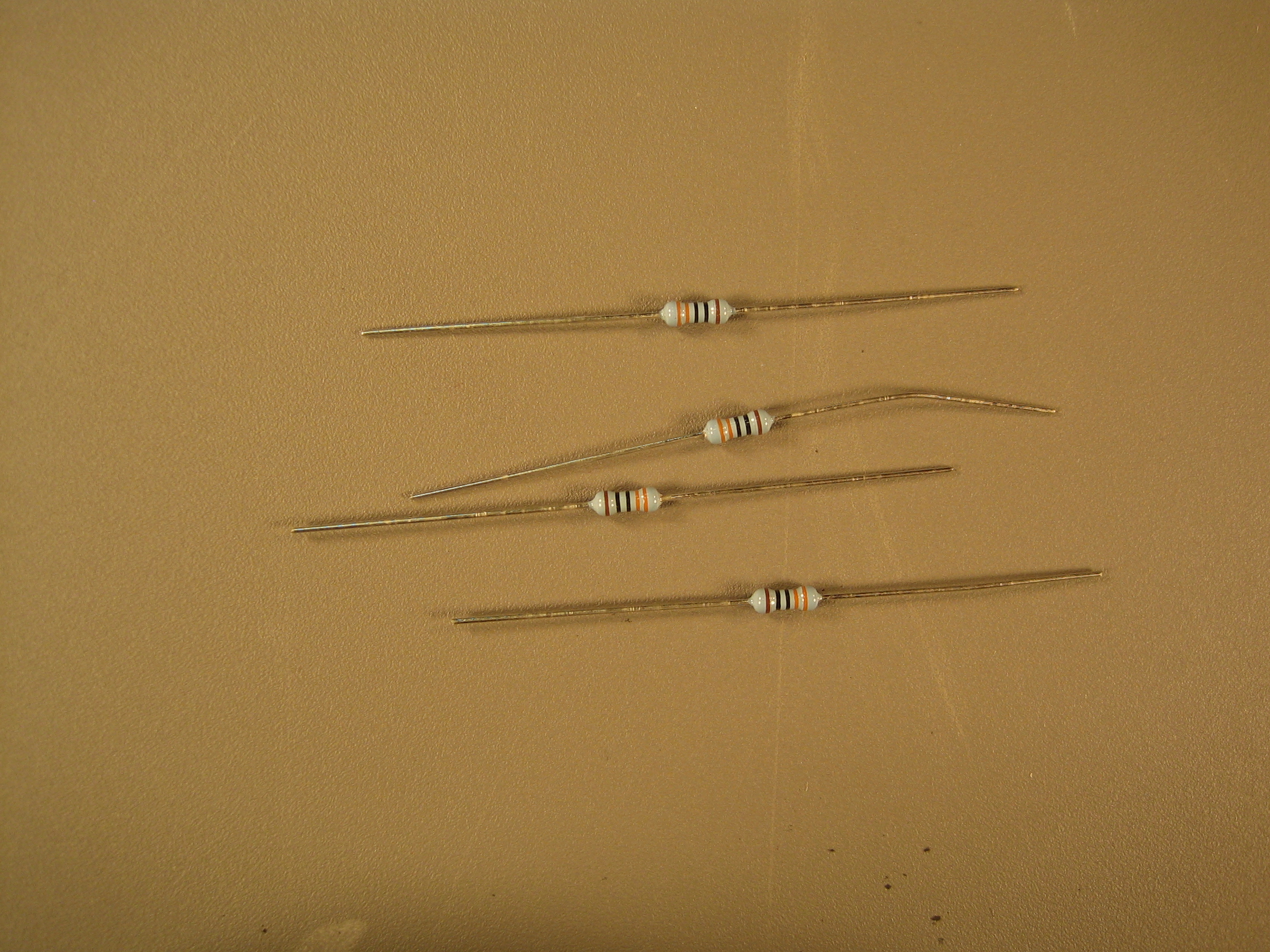
One 560-kOhm resistor (R34).
|
 |
 |
One 560-Ohm resistor (R35).
|
 |
 |
One 220-kOhm resistor (R33).
|
 |
 |
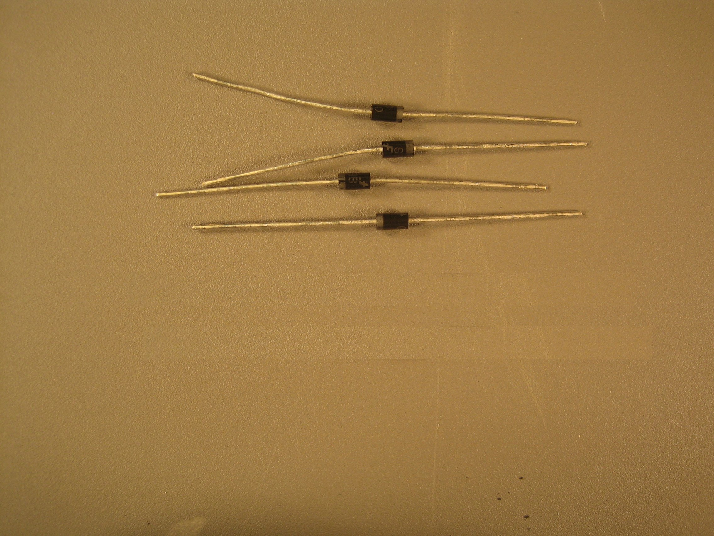
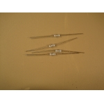
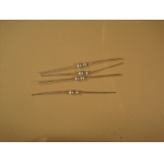
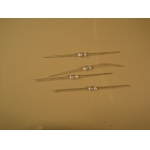
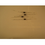
Four SB130 diodes (D1, D2, D4, D5).
|
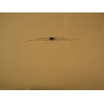 |  |
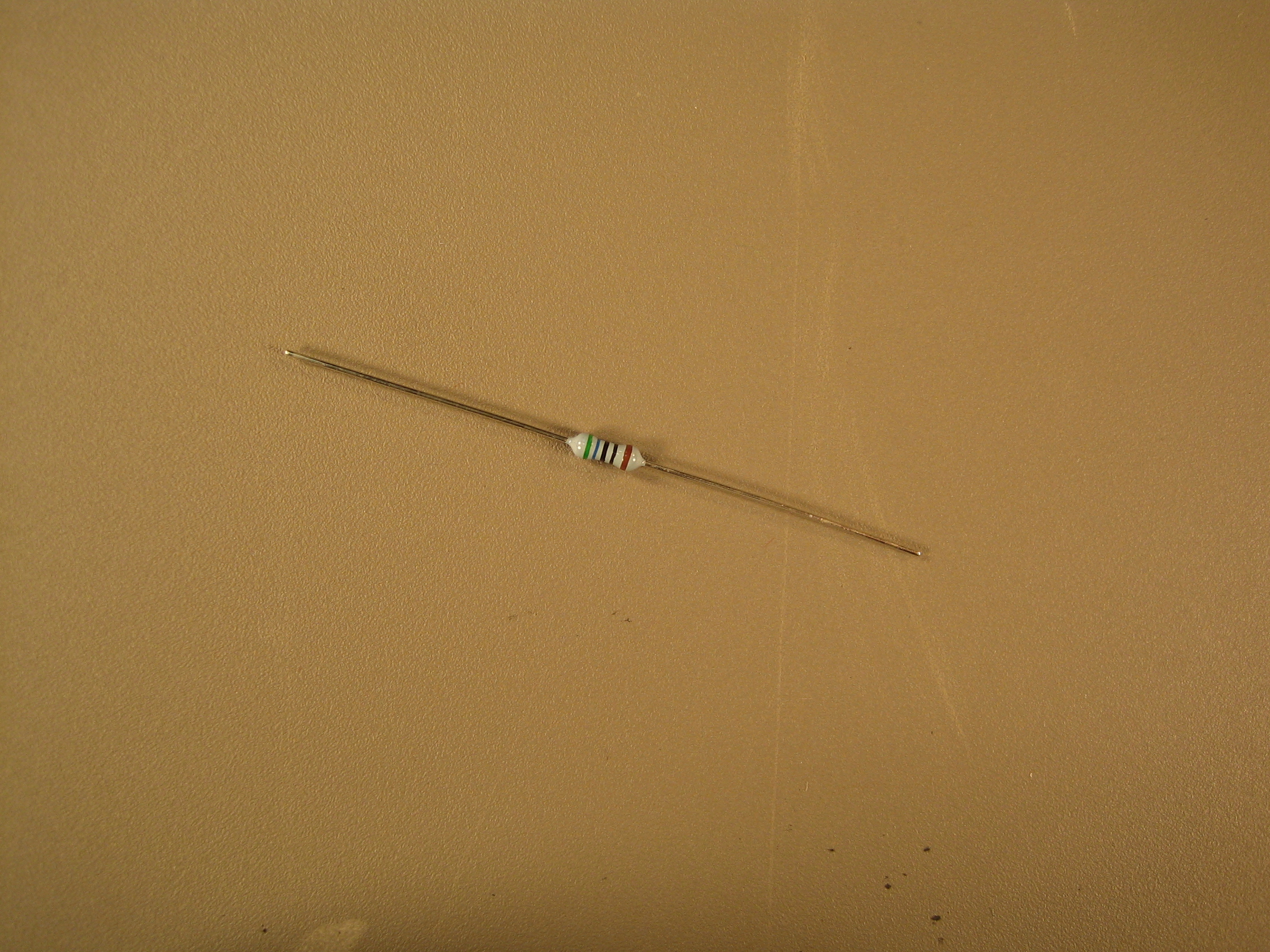
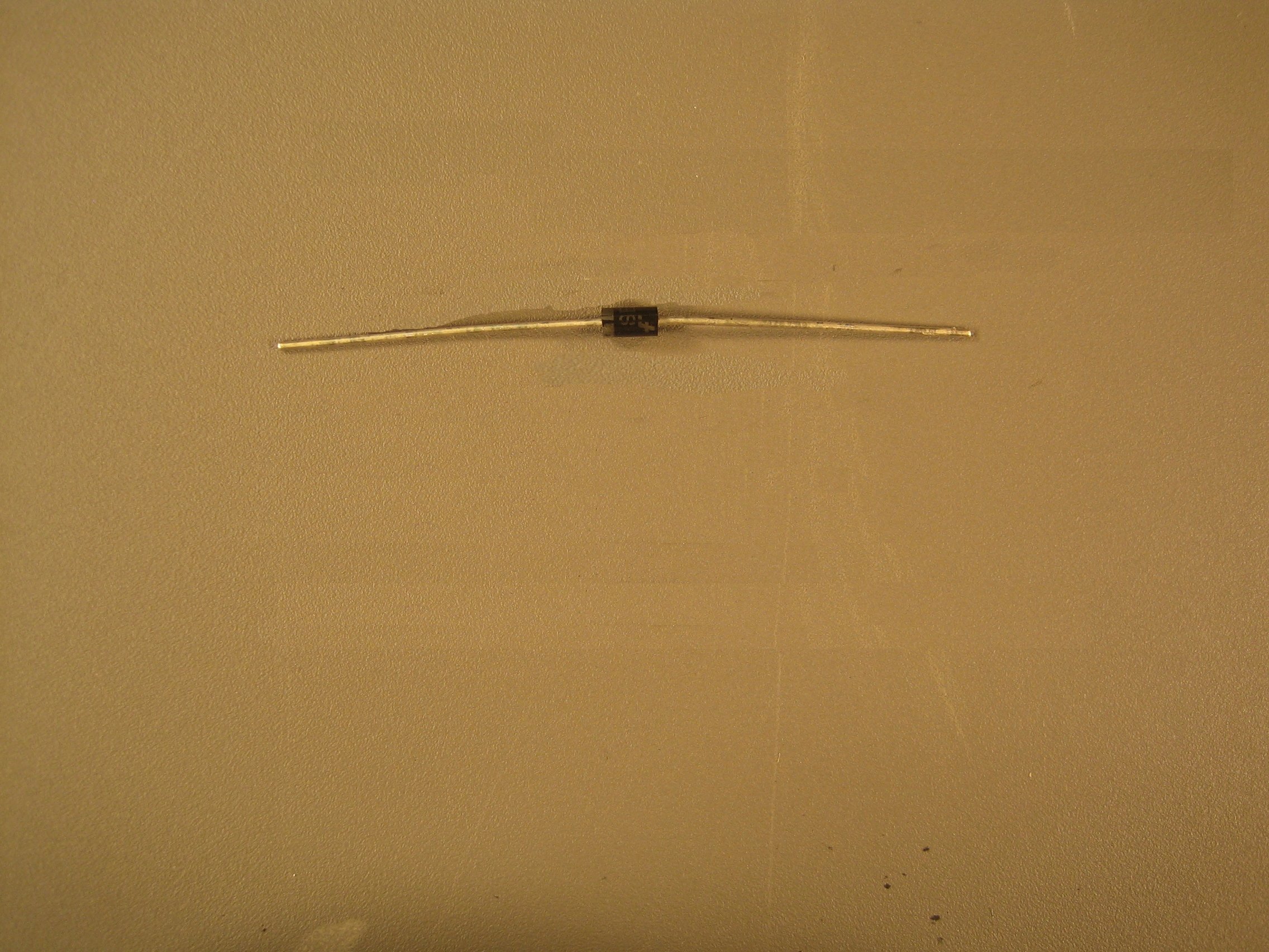
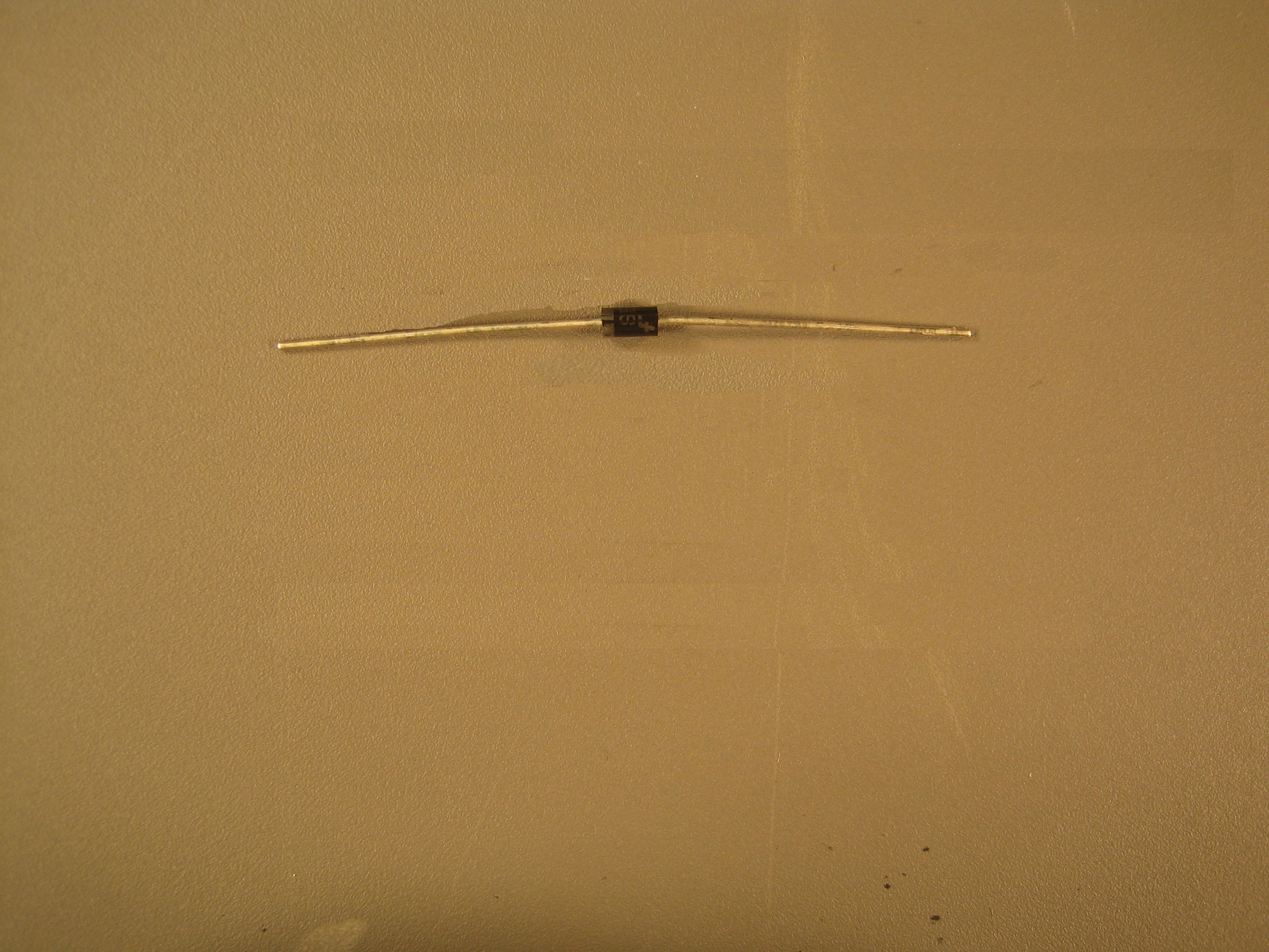
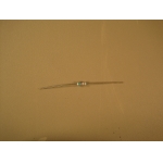
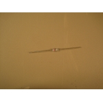
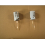
One 5.6V zener diode (D6). WARNING: The label printed on the
cicruit board reads 5.1V instead of 5.6V. Also, the diode shown in
the images following this one is of the incorrect type, but placed in
the correct position. |
 |
 |
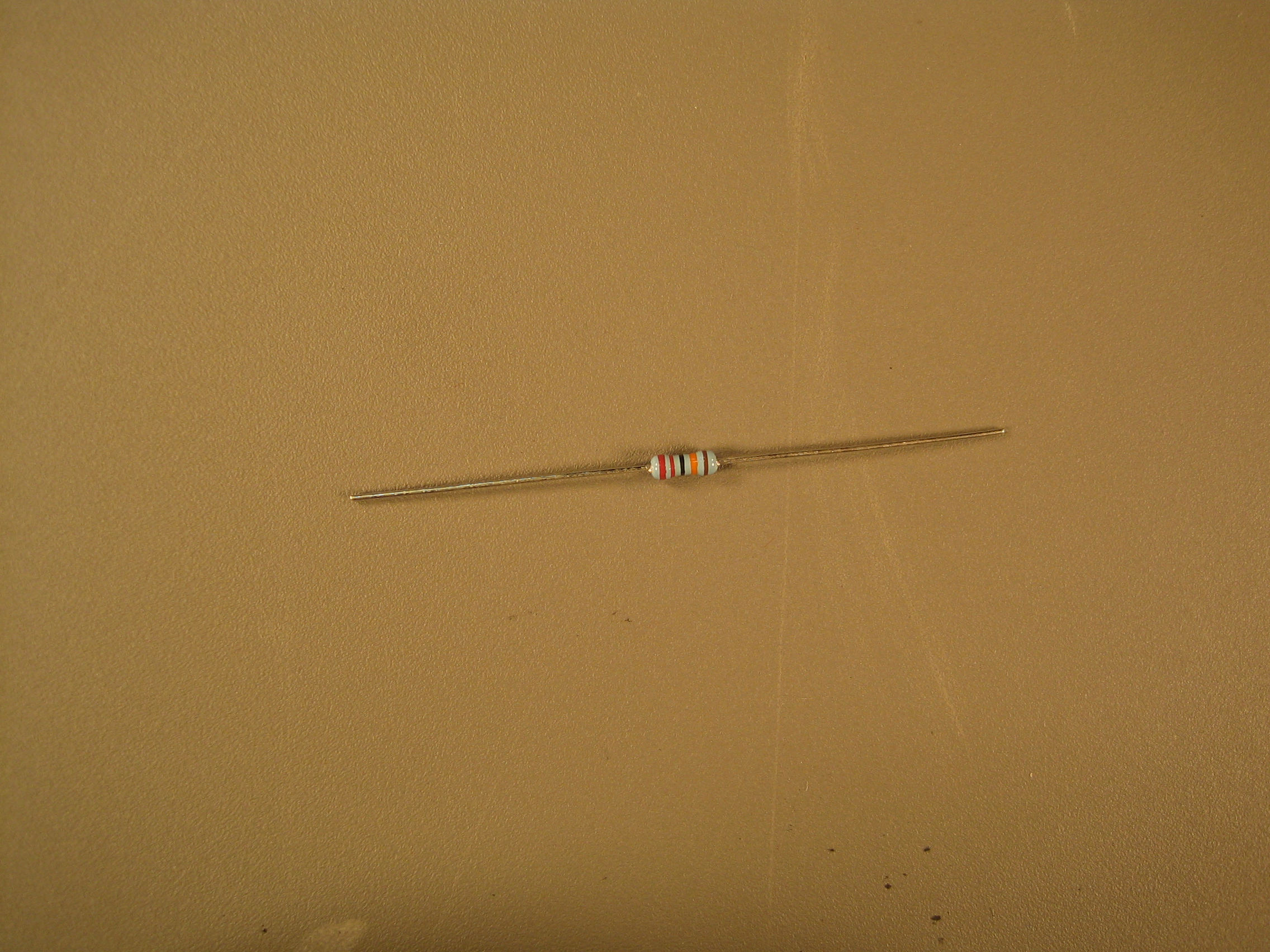
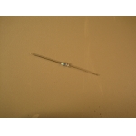
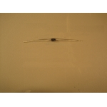
One 1N4007 1.0A diode (D3). WARNING: The diode shown in
the images following this one is of the incorrect type, but placed in
the correct position. |
 |
 |
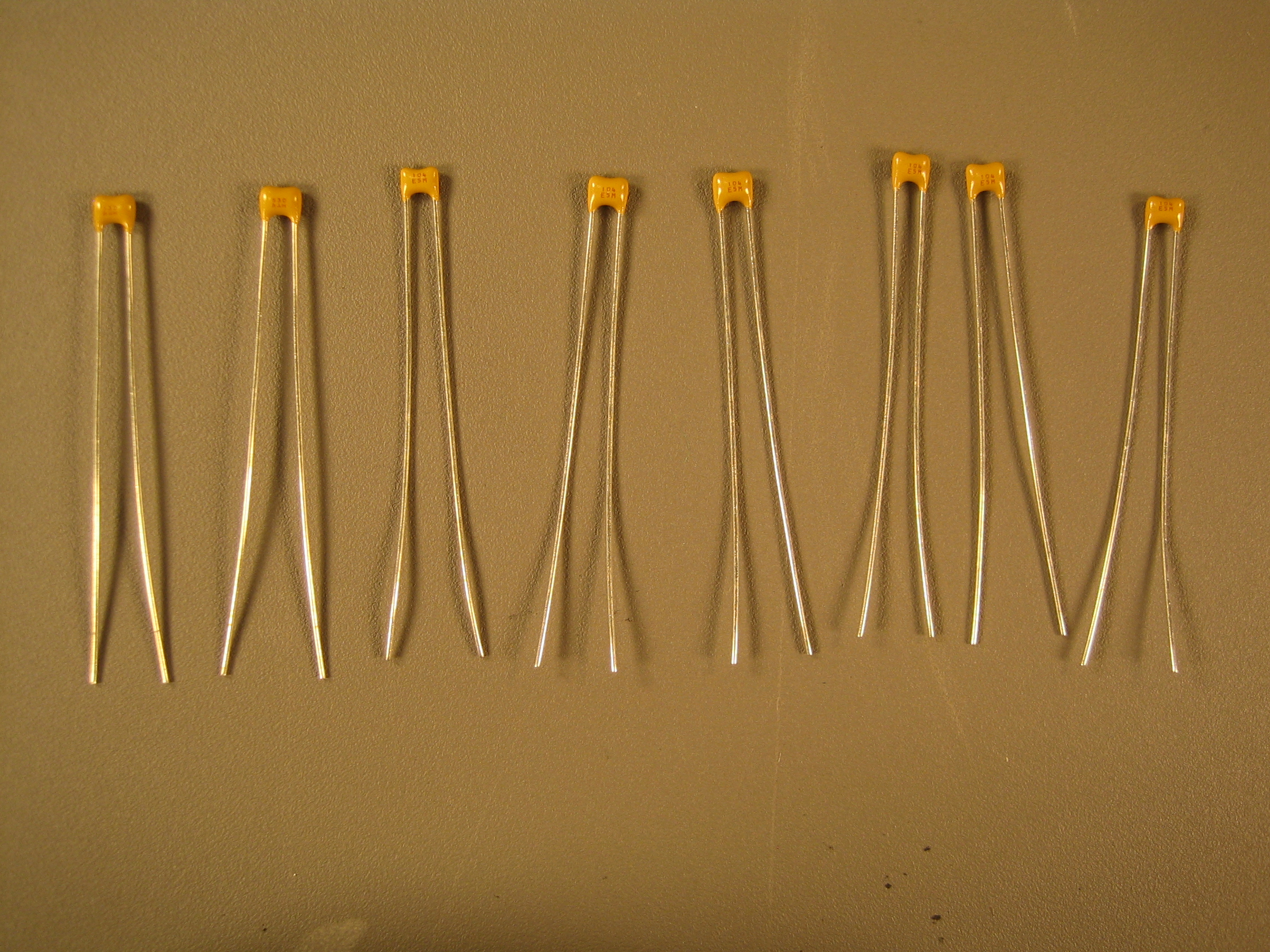
Eight 0.1-uF capacitors (C5, C11, C12, C13, C14, C15, C26, C27).
|
 |
 |
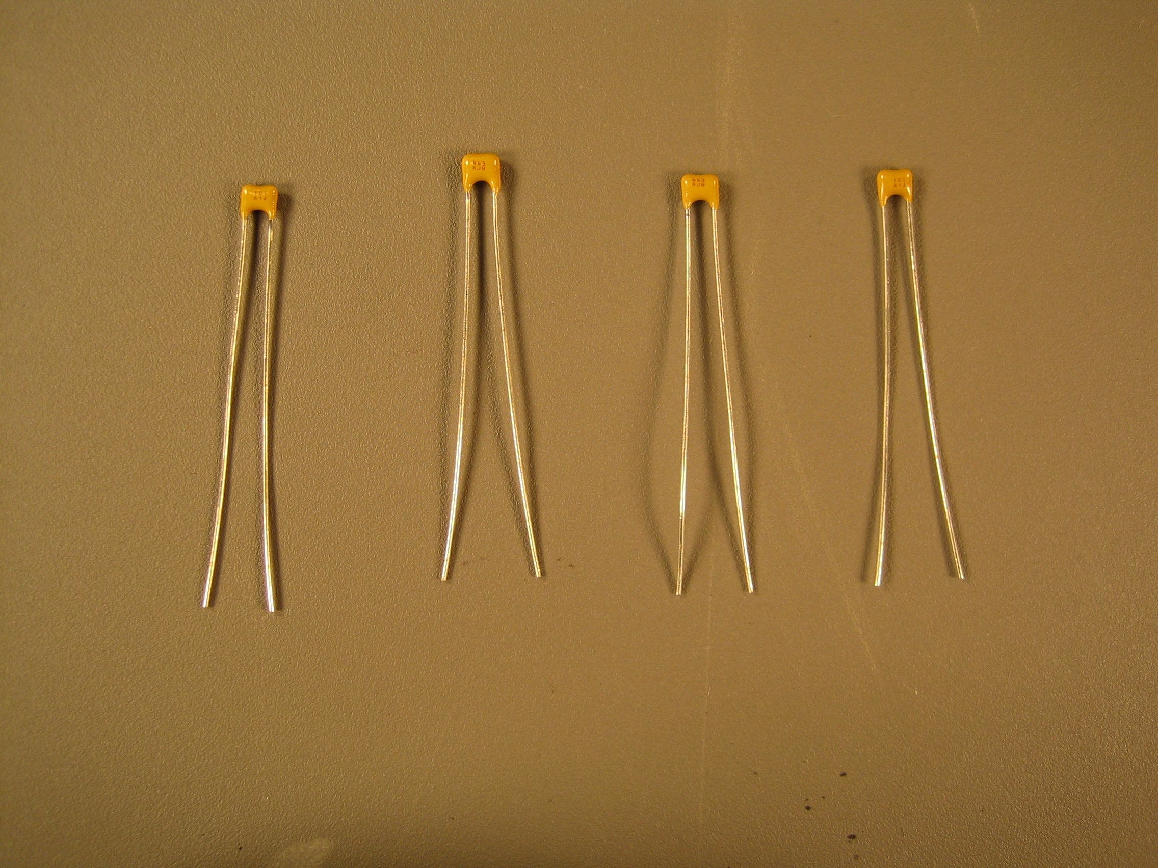
Four 100-pF capacitors (C2, C3, C8, C9).
|
 |
 |
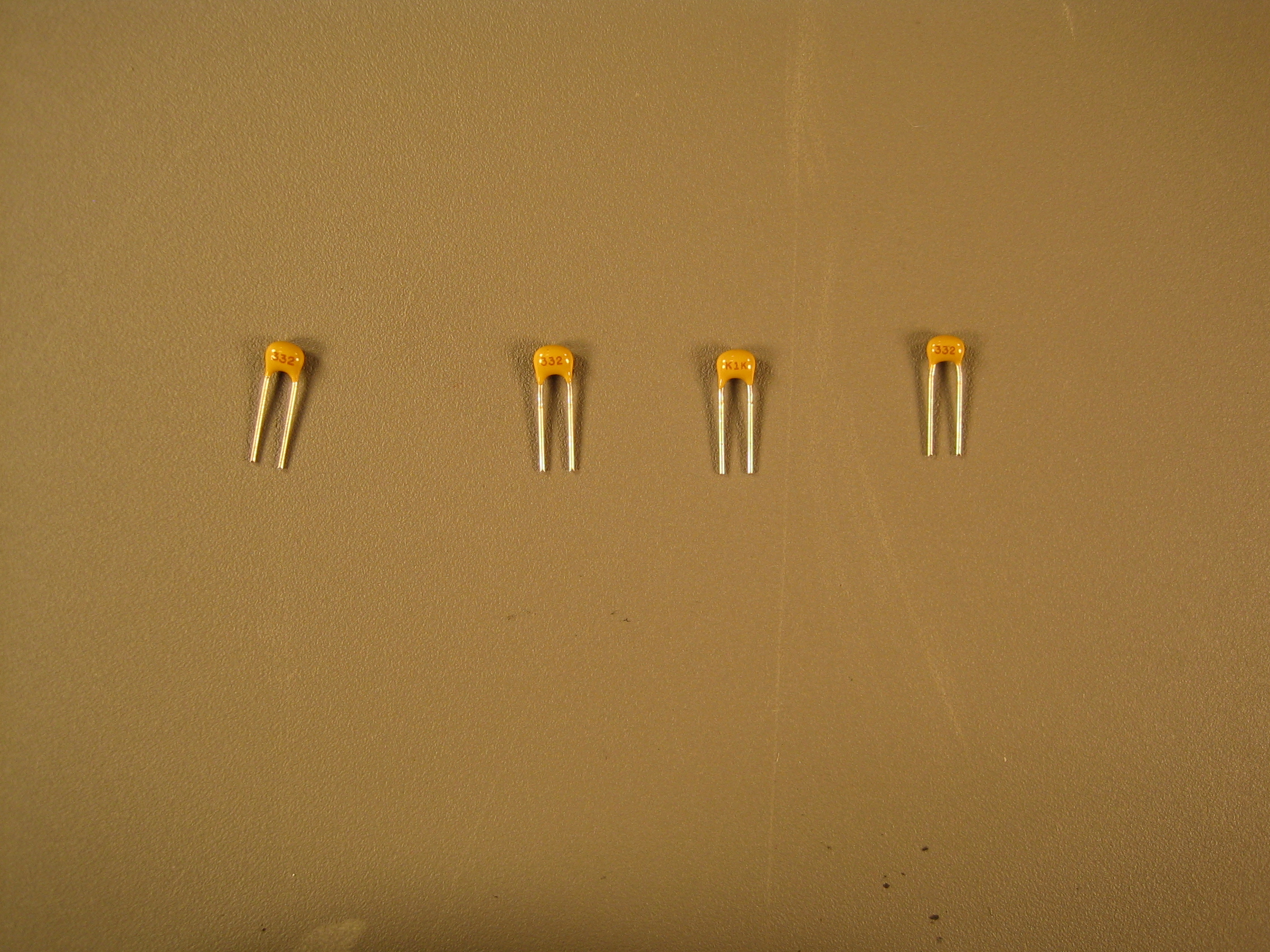
Four 3.3-nF capacitors (C1, C4, C6, C7).
|
 |
 |
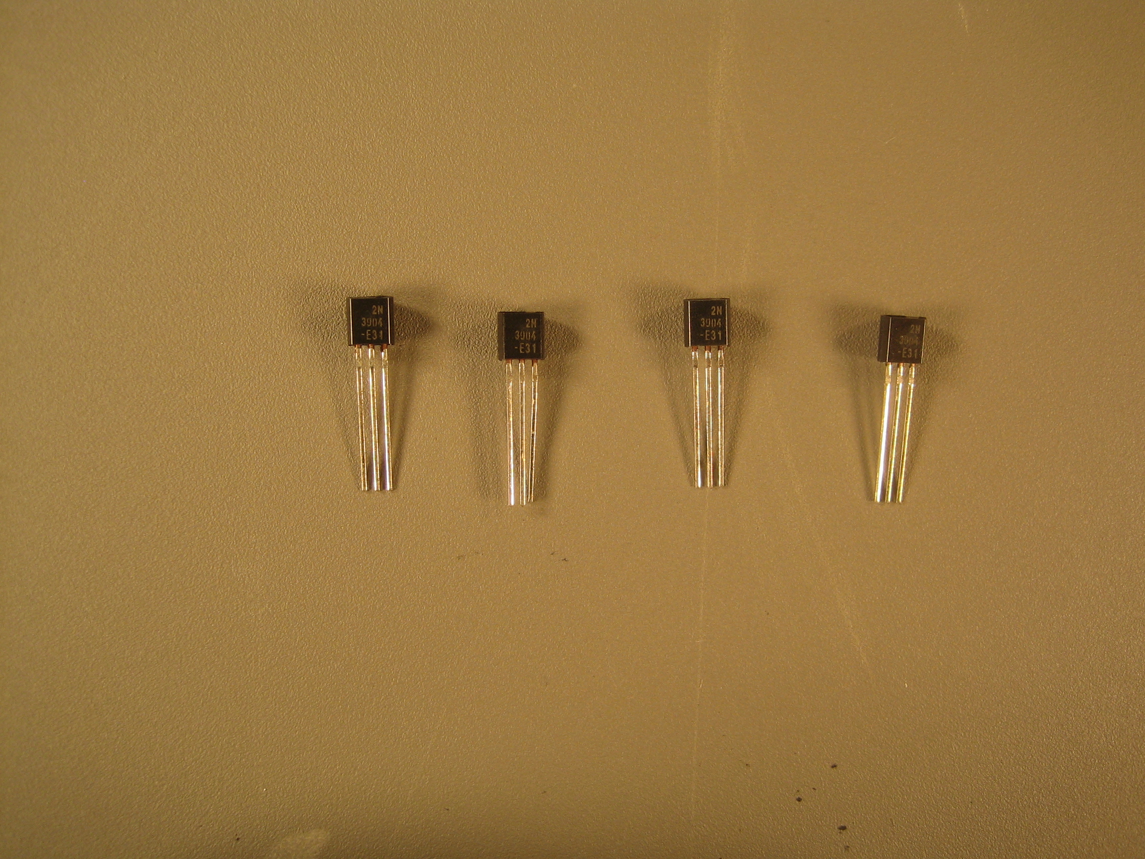
Four 2N3904 NPN transistors (Q1, Q2, Q3, Q4).
|
 |
 |
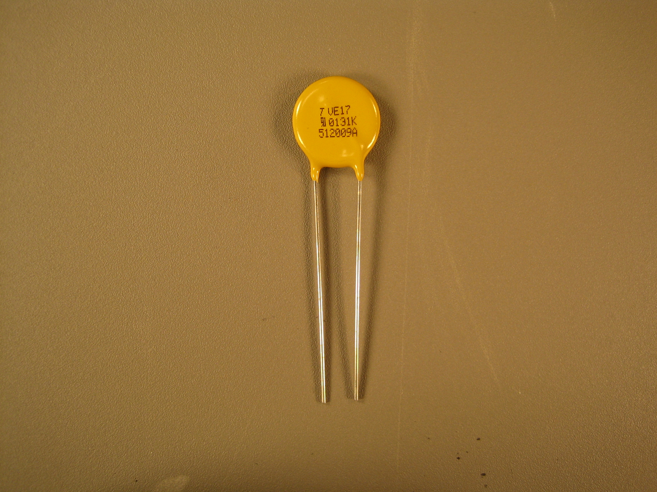
One VE17M00131K 130V radial zinc oxide +/- 10% varistor (VAR1).
|
 |
 |
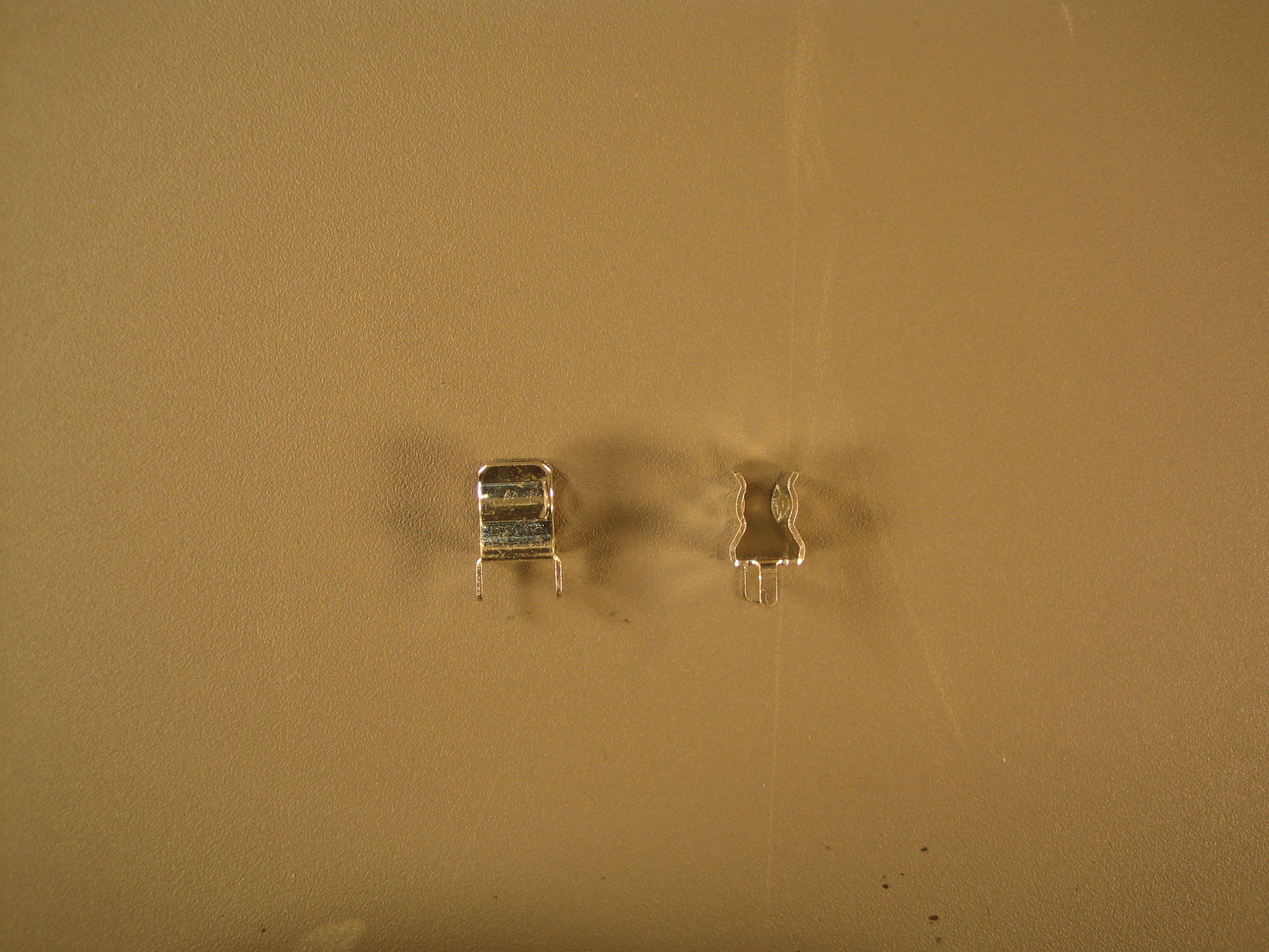
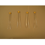
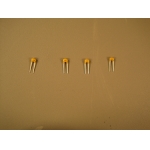
One fuse holder (F1). Comes as two separate identical pieces, one for
each side of the fuse.
|
 |
 |
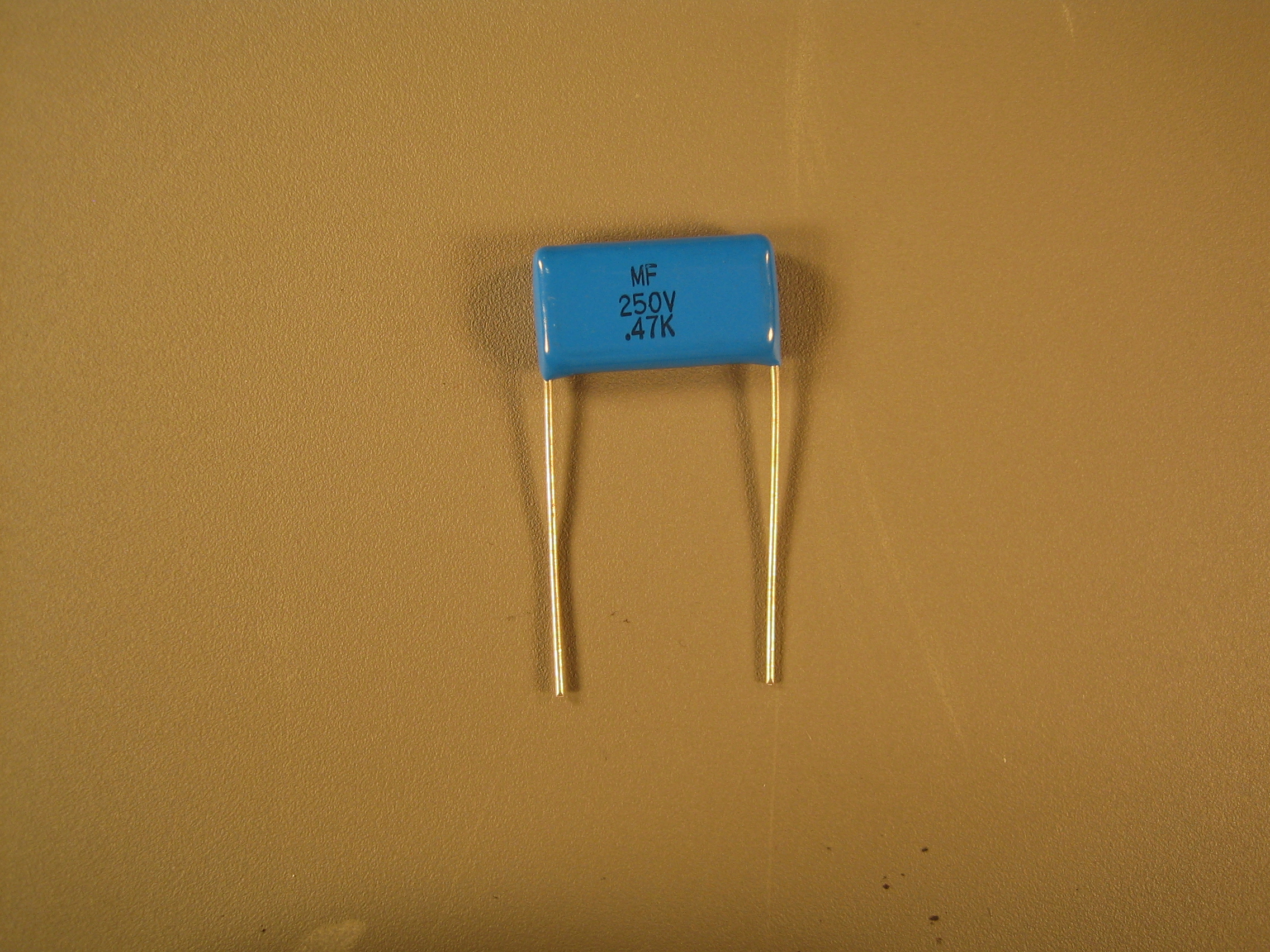
One 0.47-uF capacitor (C10).
|
 |
 |
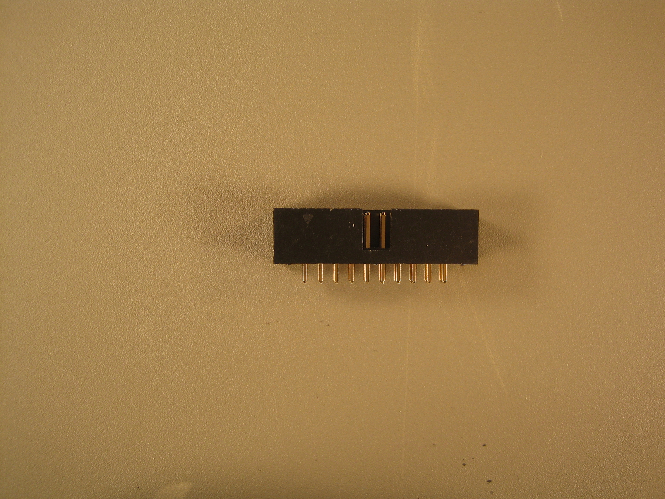
A 20-pin connector for connecting the high voltage board to the low
voltage board. WARNING: The footprint printed on the circuit board
does not show toward which side the notch in the connector should
face. The notch should face inward. See the images for details.
|
 |
 |
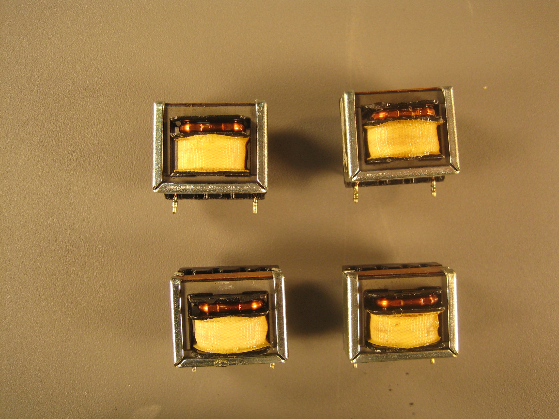
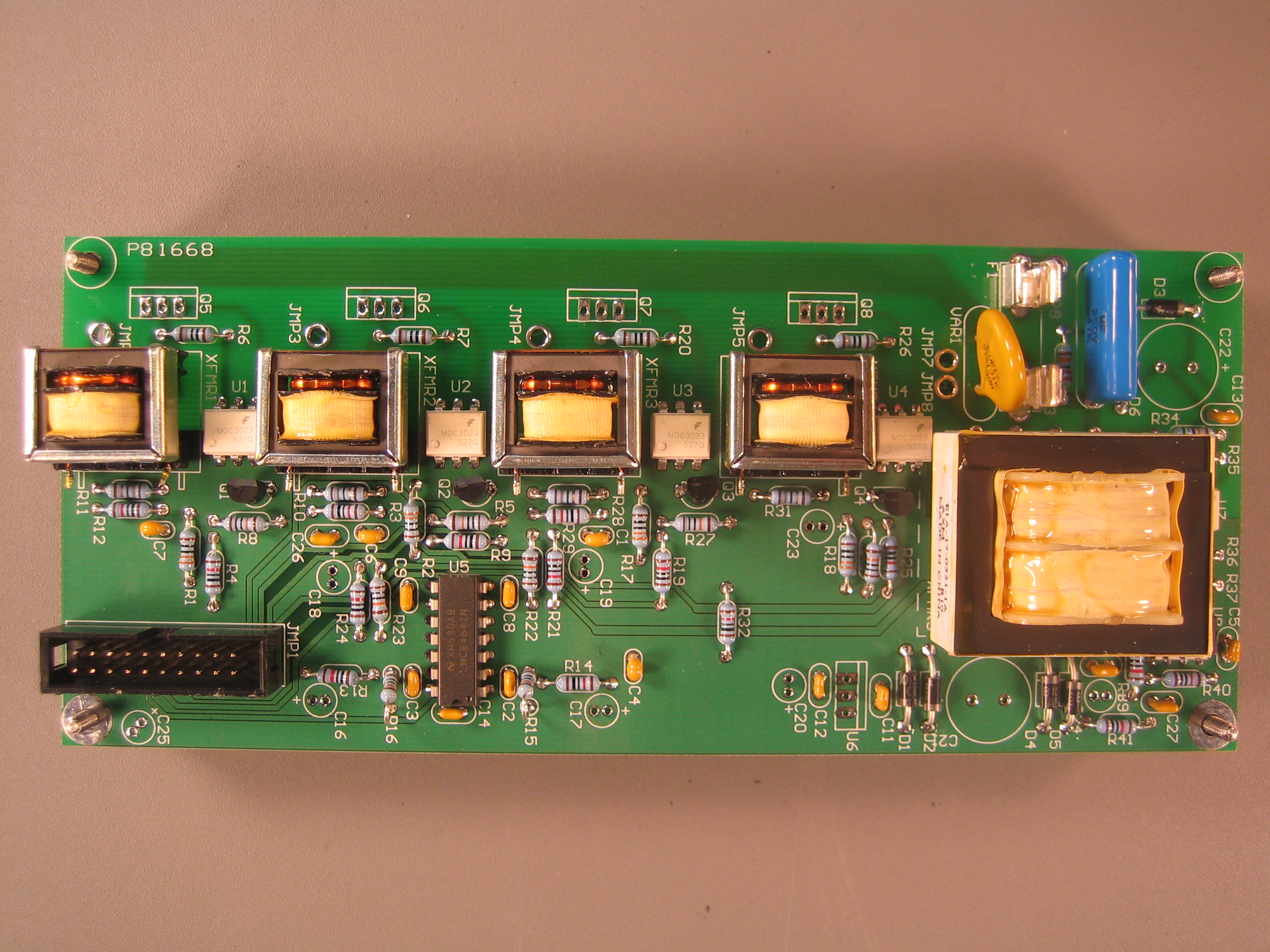
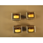
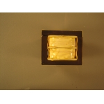
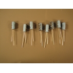
Four Triad CSE-1871 current sensor transformers (XFMR1, XFMR2, XFMR3, XFMR4).
|
 |
 |
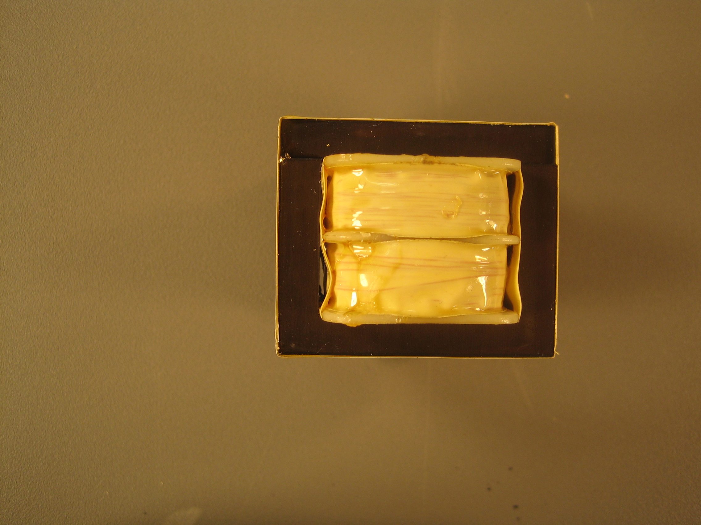
One Triad FS10-250 transformer (XFMR5).
|
 |
 |
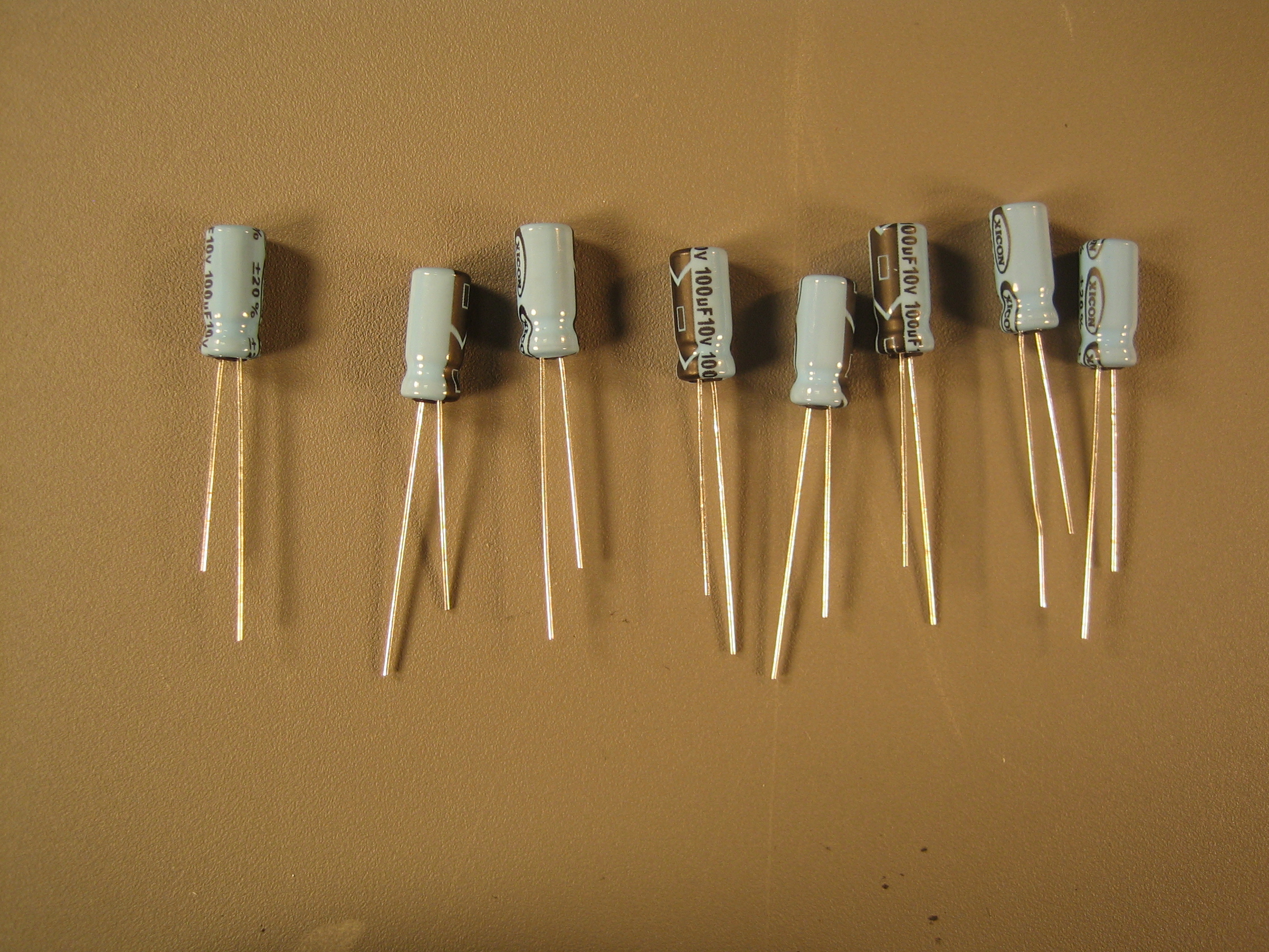
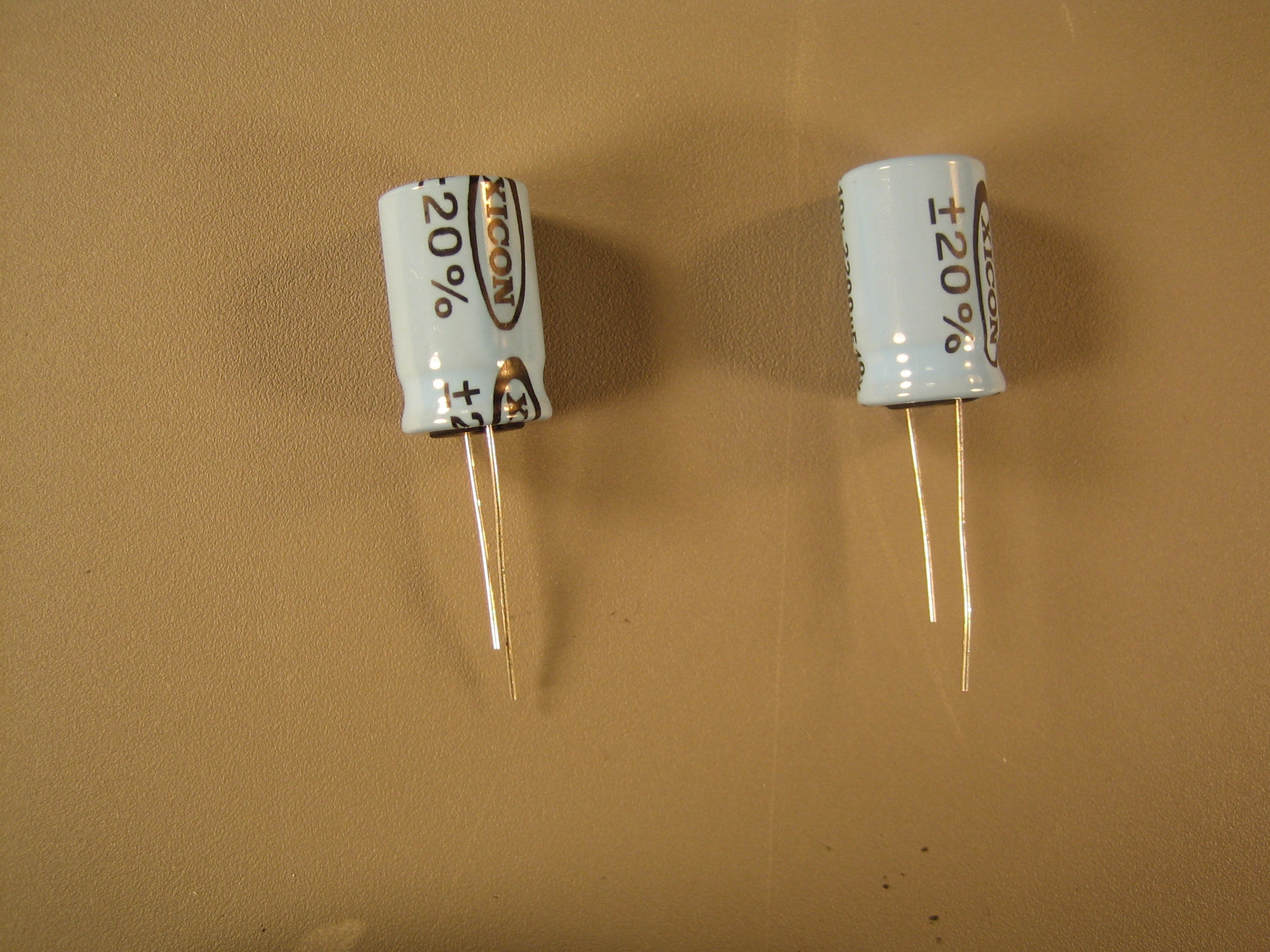
Eight 100-uF/10V electrolytic capacitors (C16, C17, C18, C19, C20,
C23, C24, C25). The minus sign on the capacitor should face away from
the plus sign on the footprint printed on the circuit board.
|
 |
 |
Two 2200-uF/10V electrolytic capacitors (C21, C22). The minus sign on
the capacitor should face away from the plus sign on the footprint
printed on the circuit board.
|
 |
|
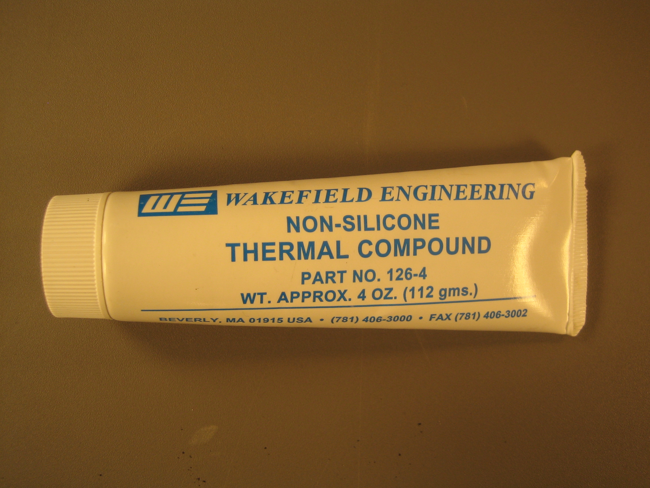
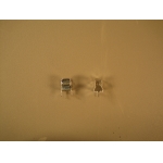
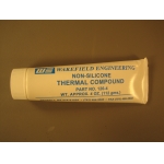
Thermal heat sink paste for better conducting heat between parts and
their heat sinks. See below.
|
 |
 |
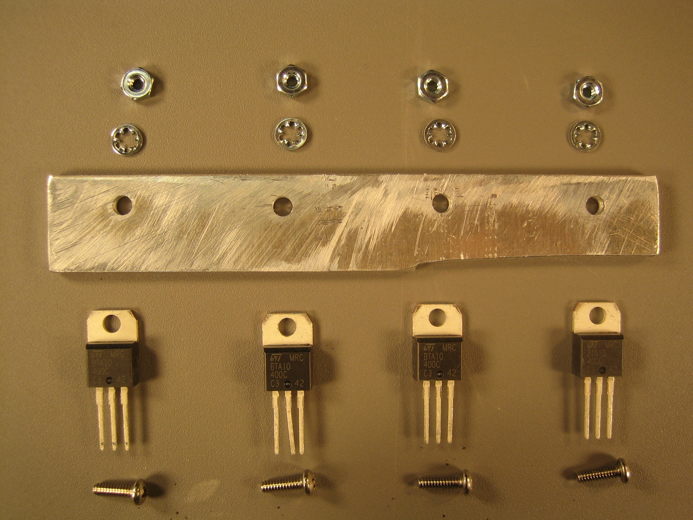
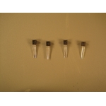
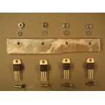
Four BTA10-400C triacs connected to an aluminum heat sink with 4-40
3/8" screws, 4-40 nuts, 4-40 inner teeth lock washers and heat sink
paste (Q5, Q6, Q7, Q8). Loosely attach the triacs to the heat sink
before soldering the triacs to the board. Tighten the screws holding
the heat sink to the triacs after the triacs have been soldered to the
board.
|
 |
 |
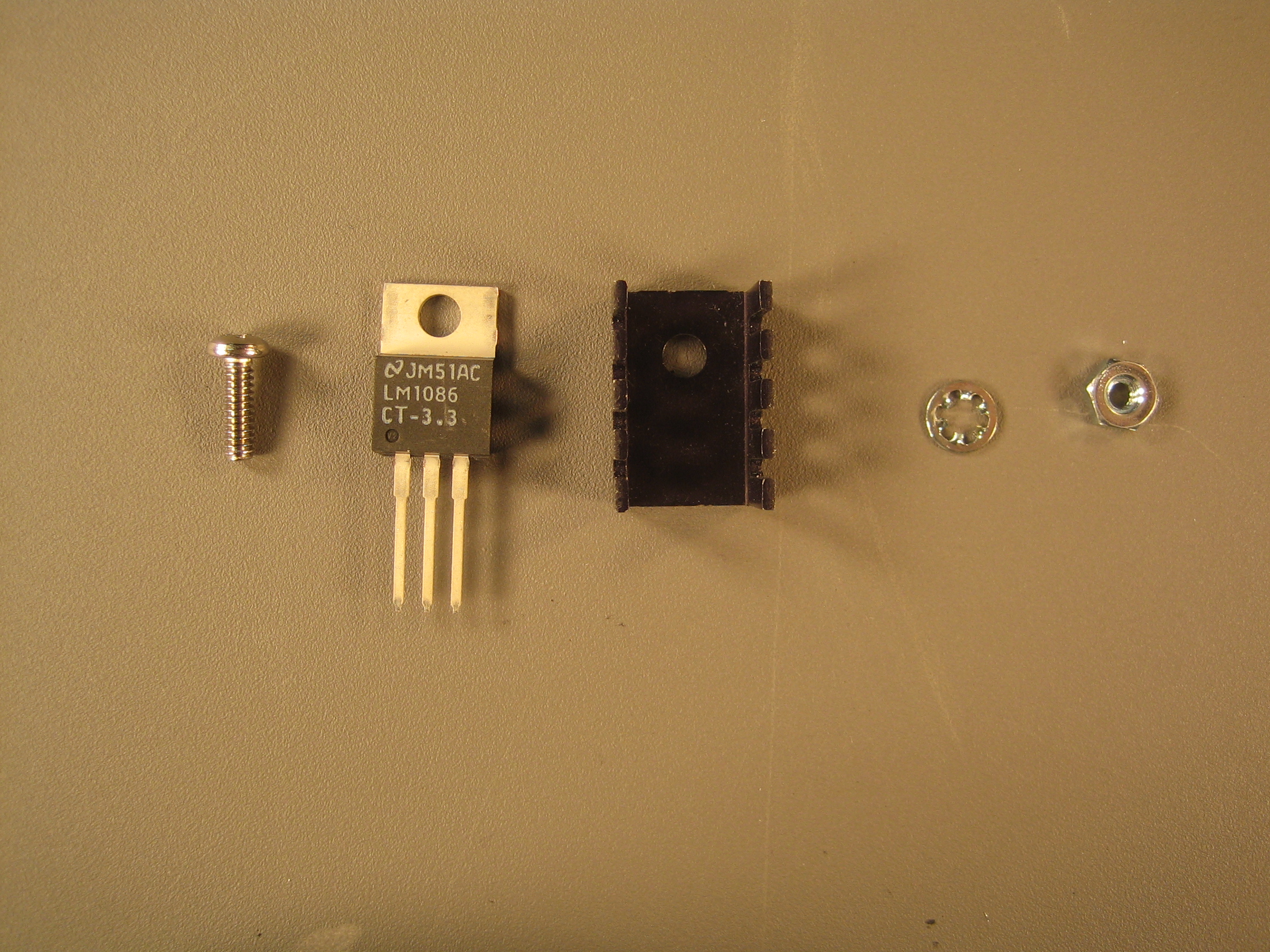
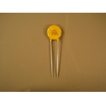
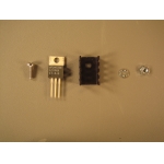
One LM1086 voltage regulator connected to a heat sink with a 4-40
3/8" screw, 4-40 nut, 4-40 inner teeth lock washer and heat sink
paste (U6). The body of the voltage regulator should be hidden in the
heat sink.
|