| This guide illustrates how to put together a low
voltage board for the Plug, except for some parts having to do with
the radio, vibration sensor and speaker. These parts will be added
later. |
| Plug Low Voltage
Board Schematic [PDF]. |
| COMPONENT | PLACEMENT |
DESCRIPTION (parity matters if text is highlighted yellow)
|
|
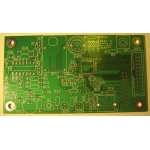 |
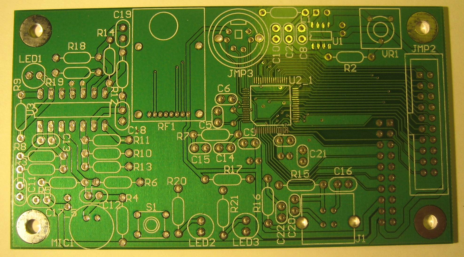
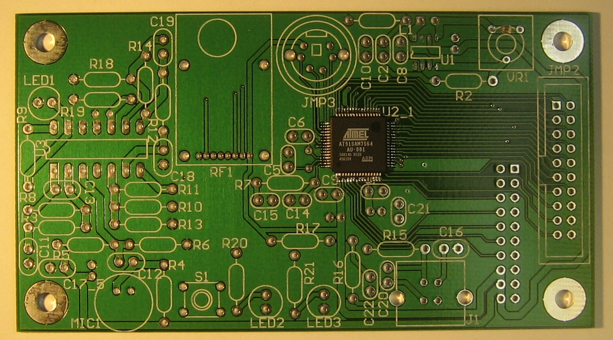
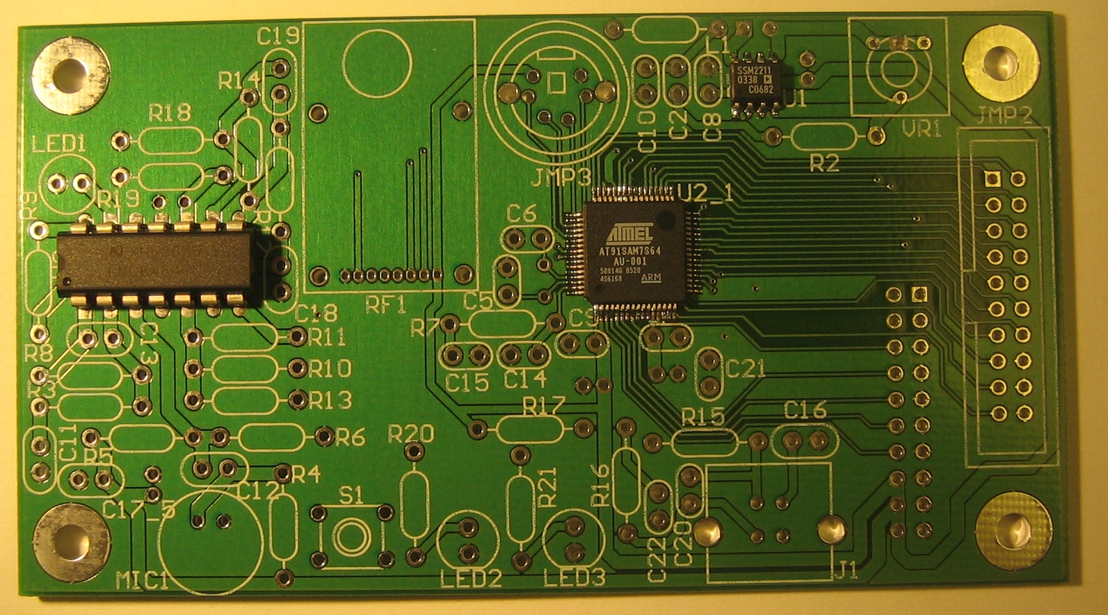
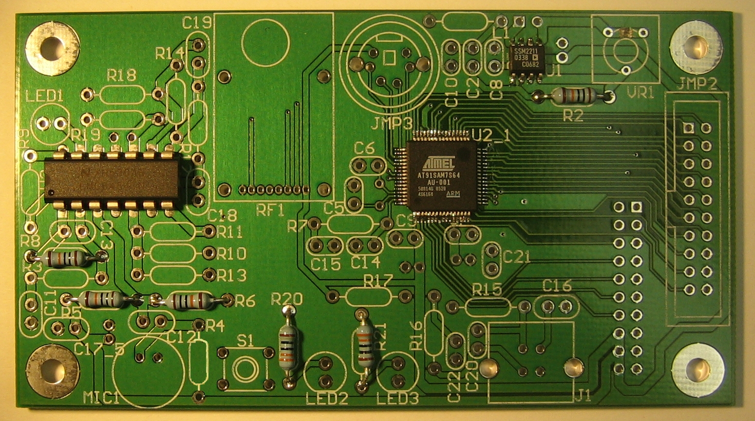
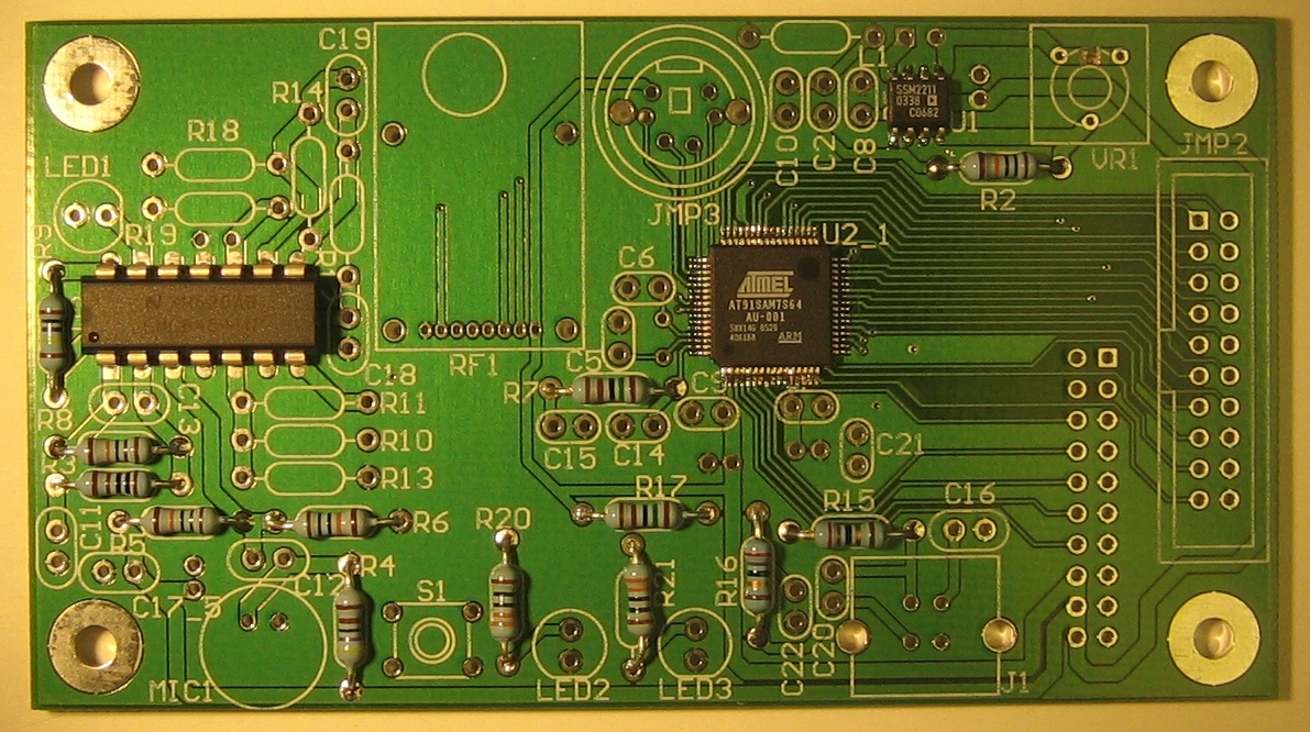
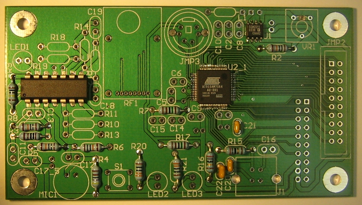
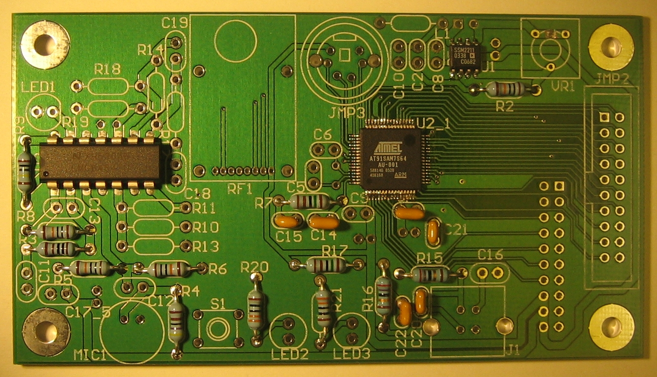
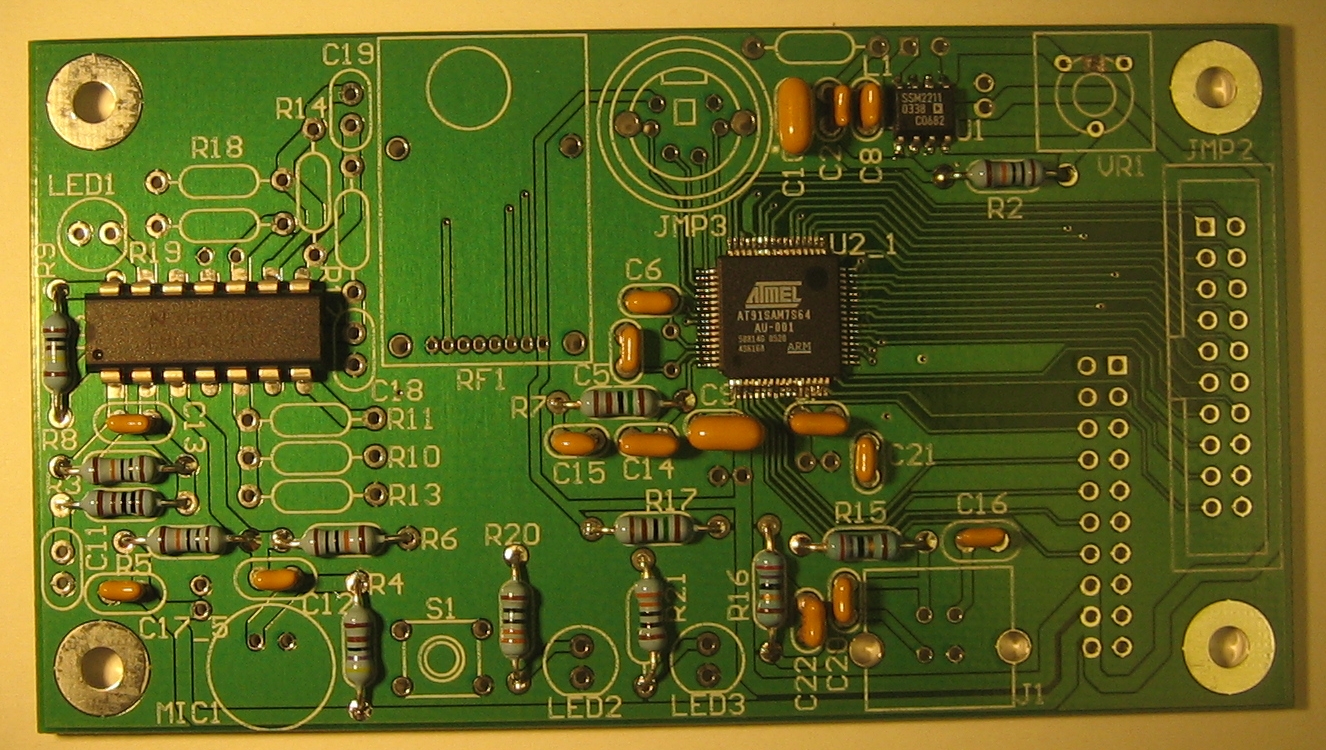
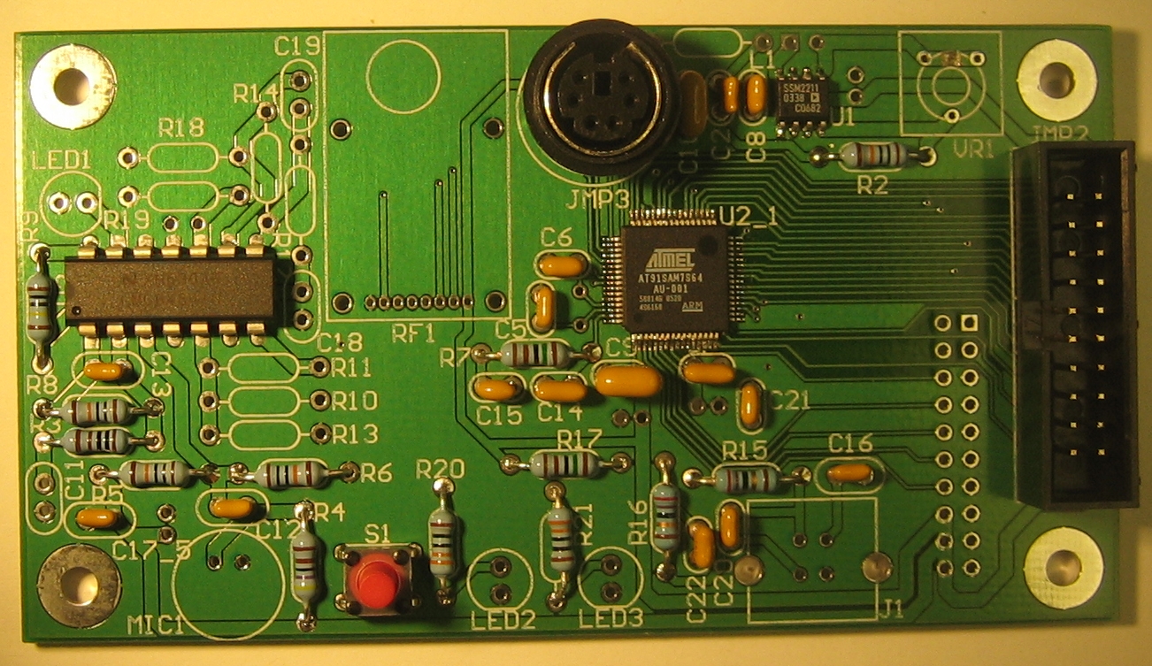
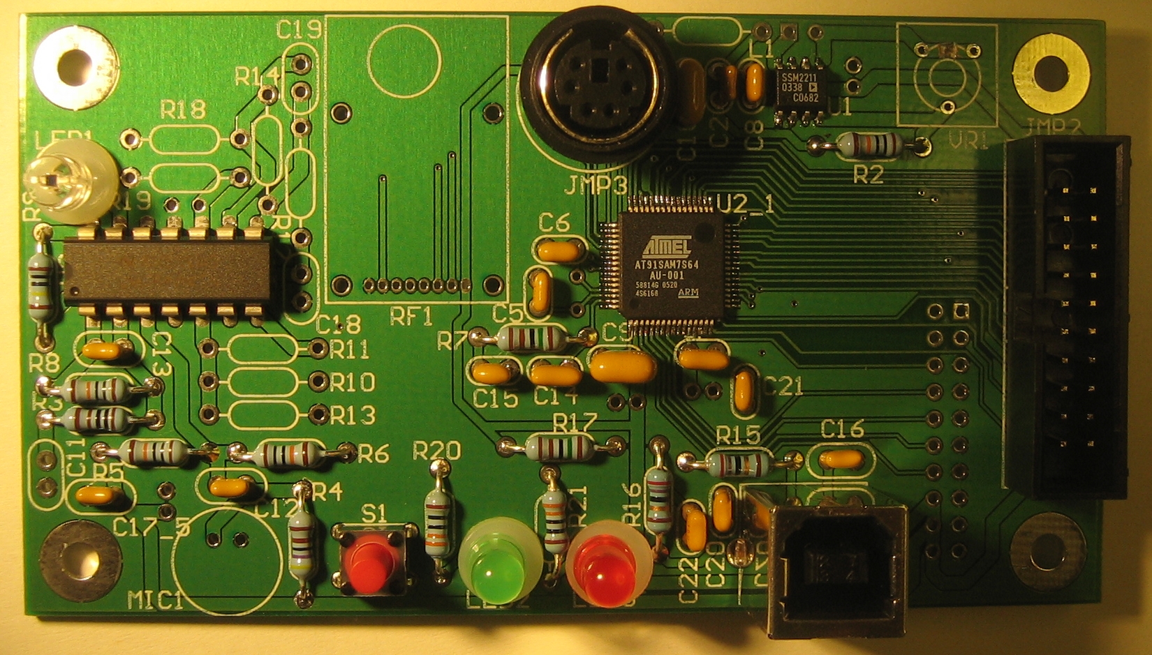
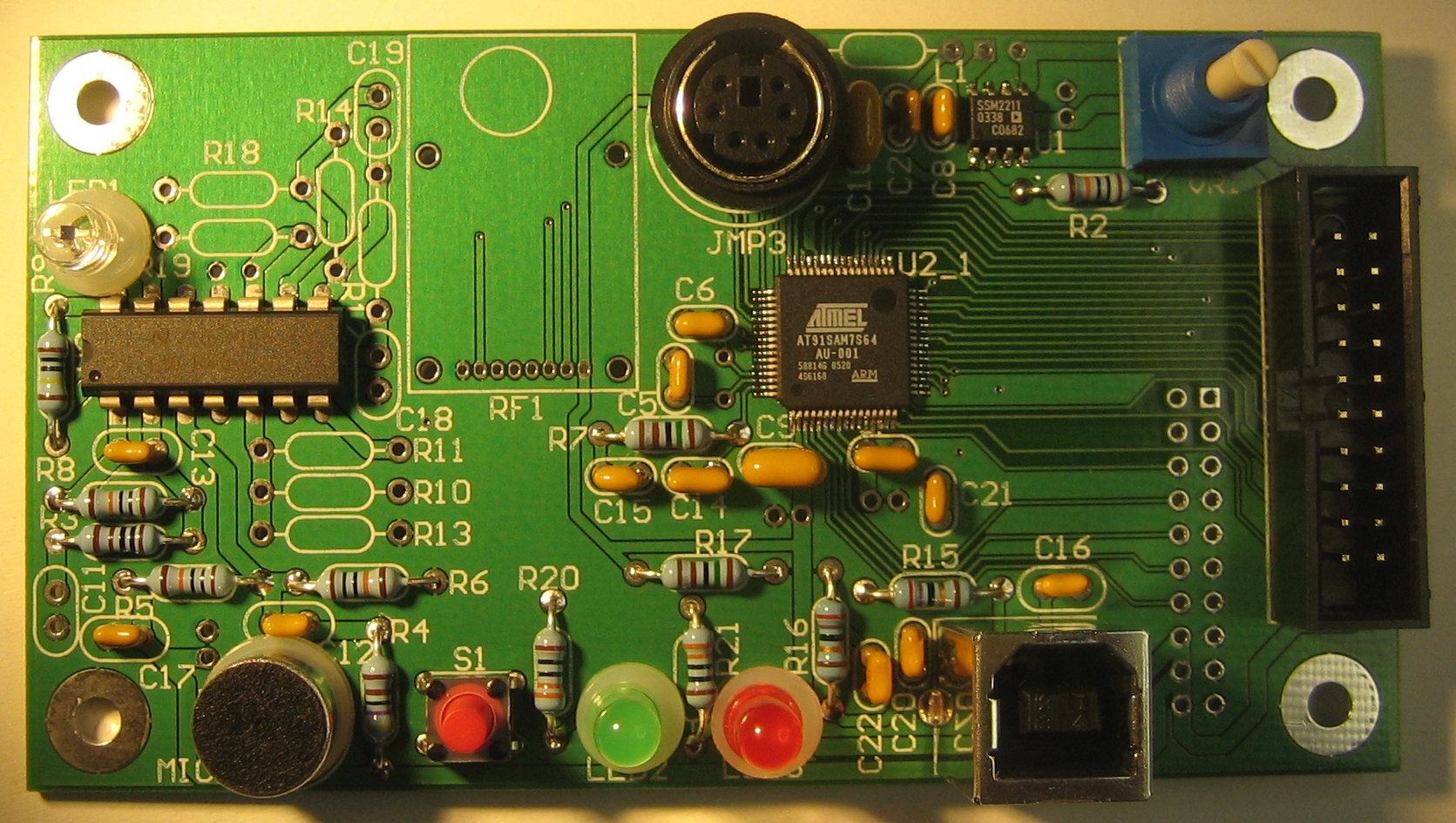
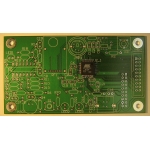
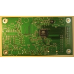
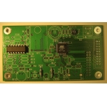
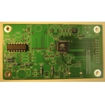
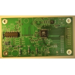
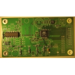
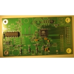
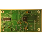
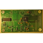
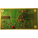
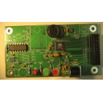
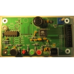
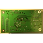
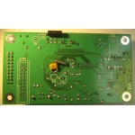
The top side of the plug low voltage printed circuit board before any
components have been added. Use a metal file to make the edges
smooth.
|
 |
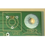 |
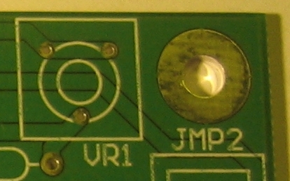
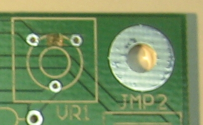
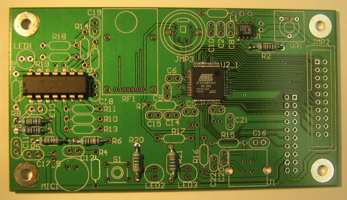
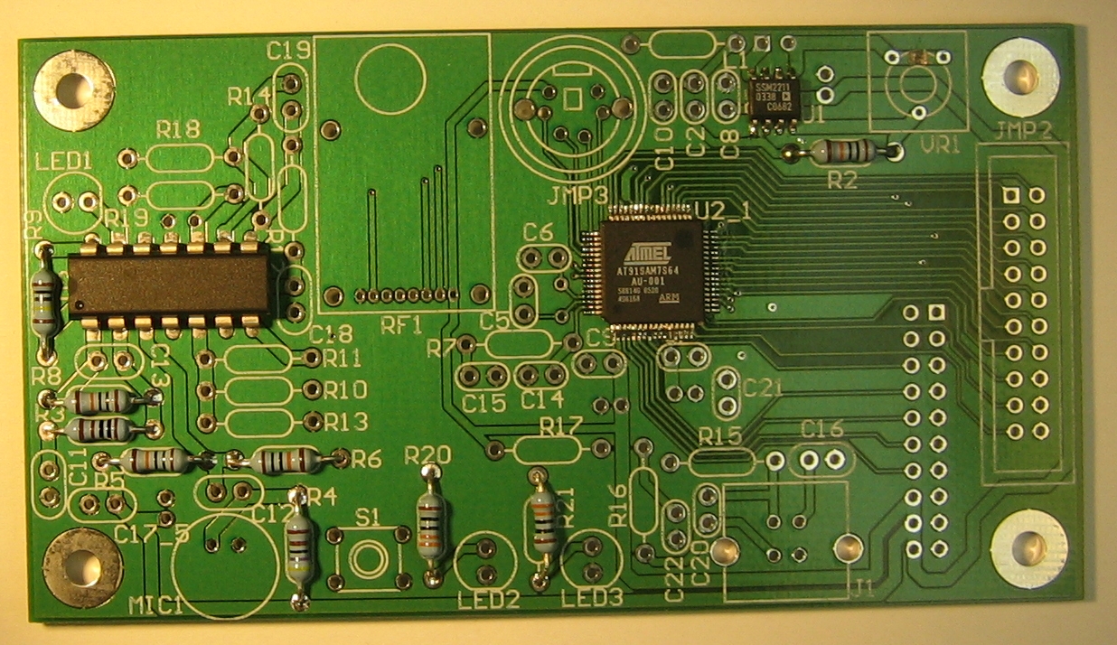
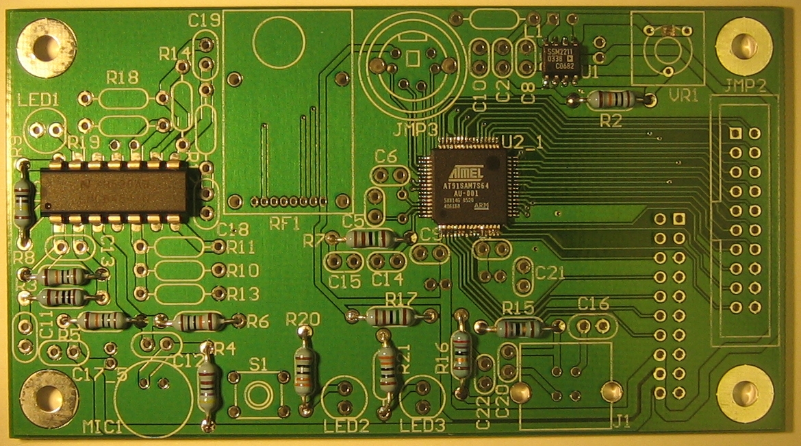
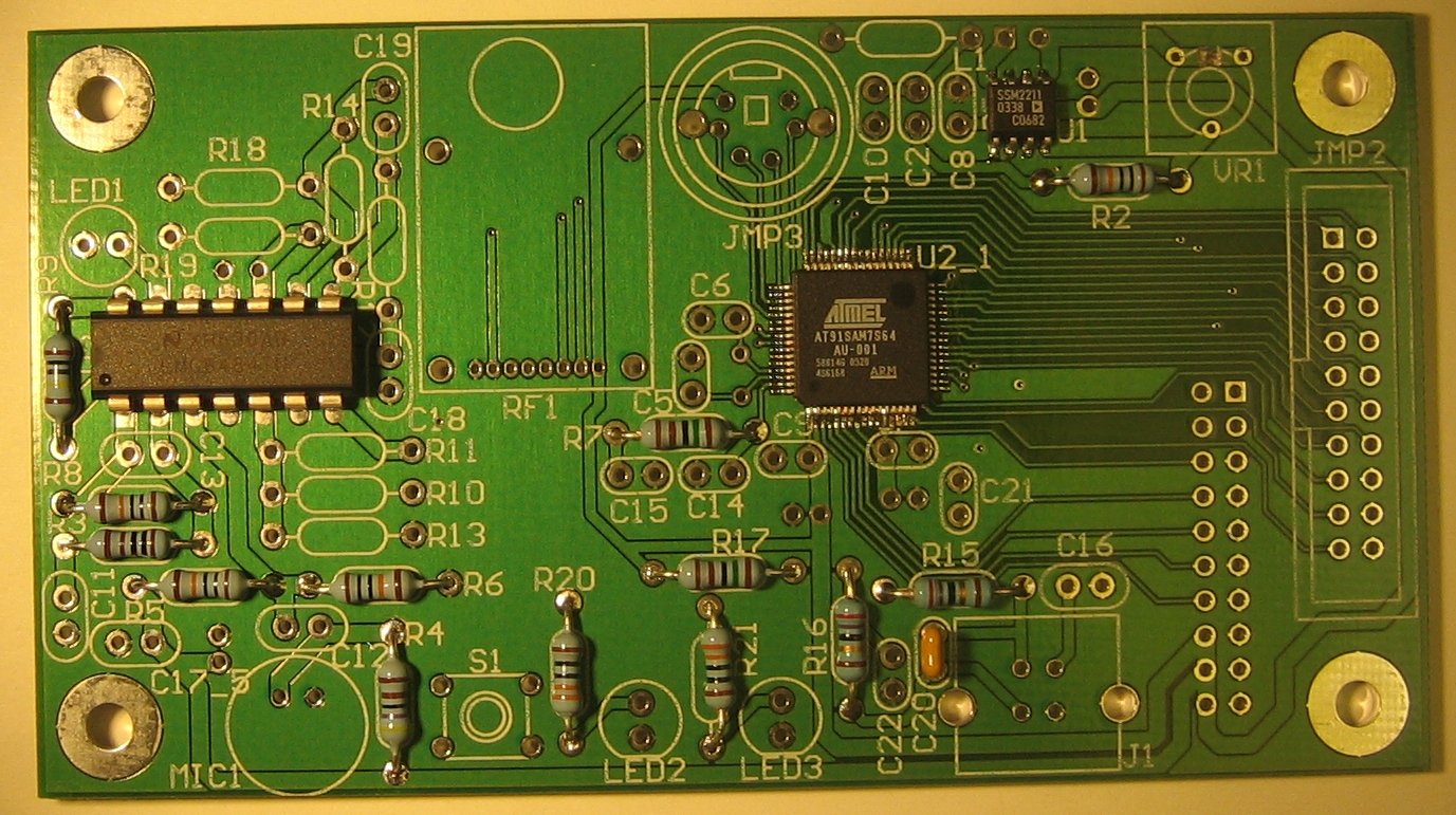
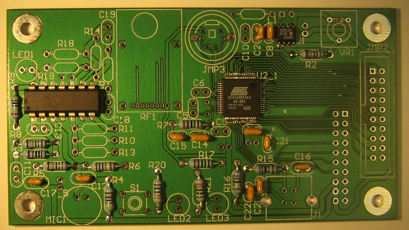
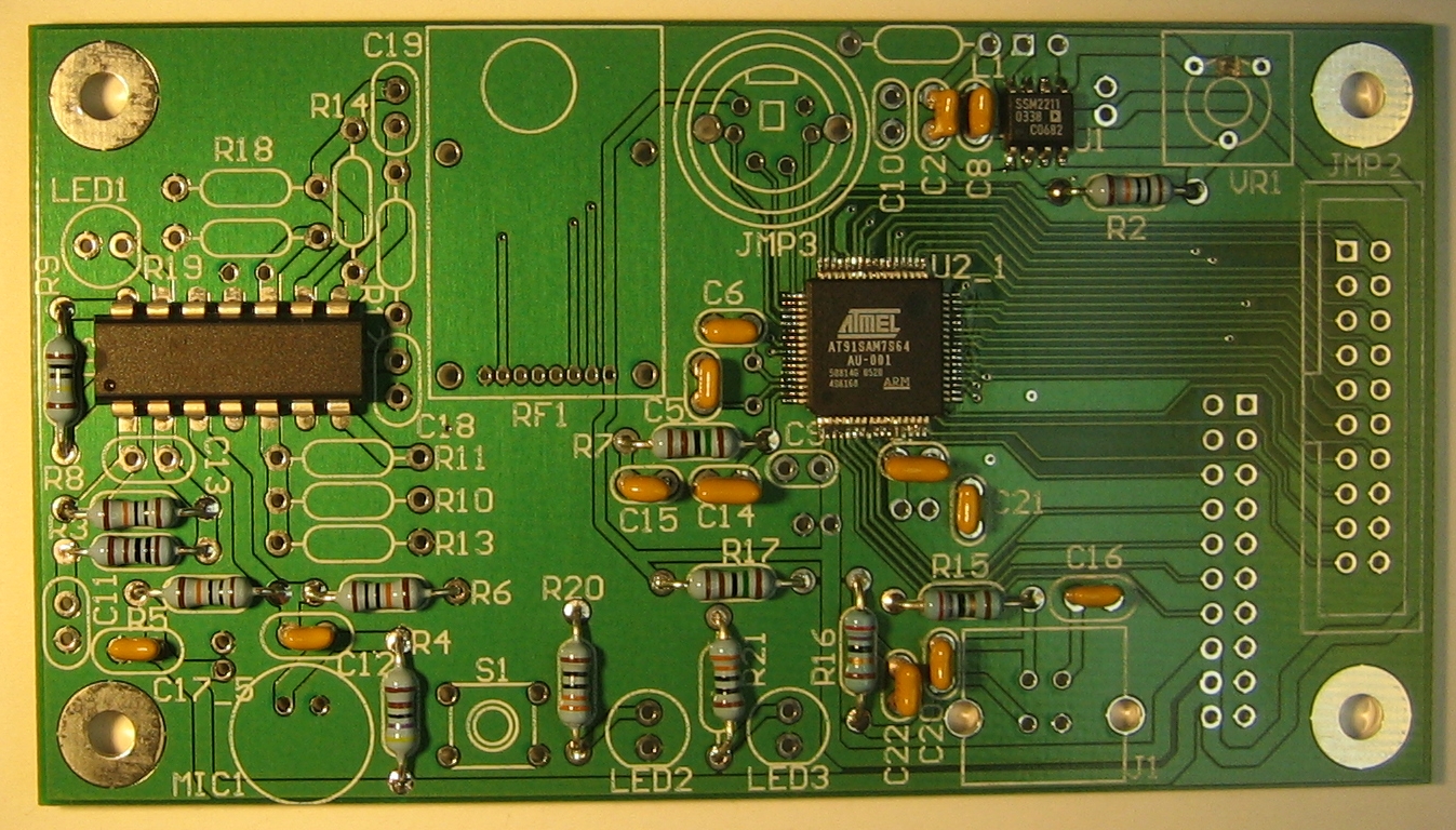
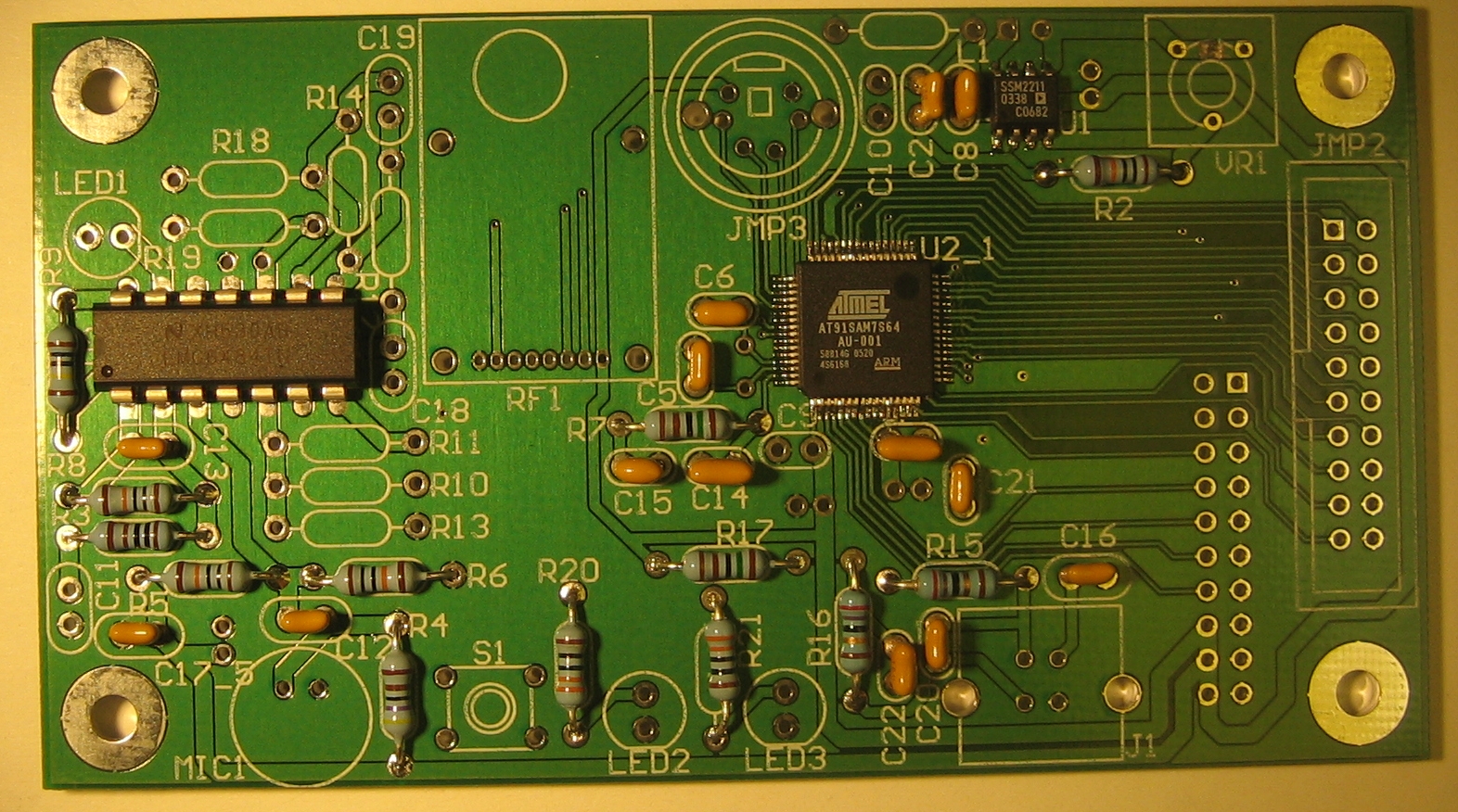
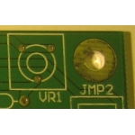
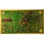
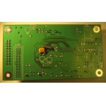
There is a minor error in the design of the printed circuit board. To
fix this error, you will need to use a sharp blade to cut a single
trace, thereby severing an electrical connection. The left-most image
shows the trace before being cut, the right-most after being cut.
|
 |
 |
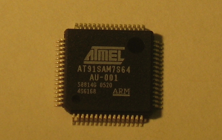
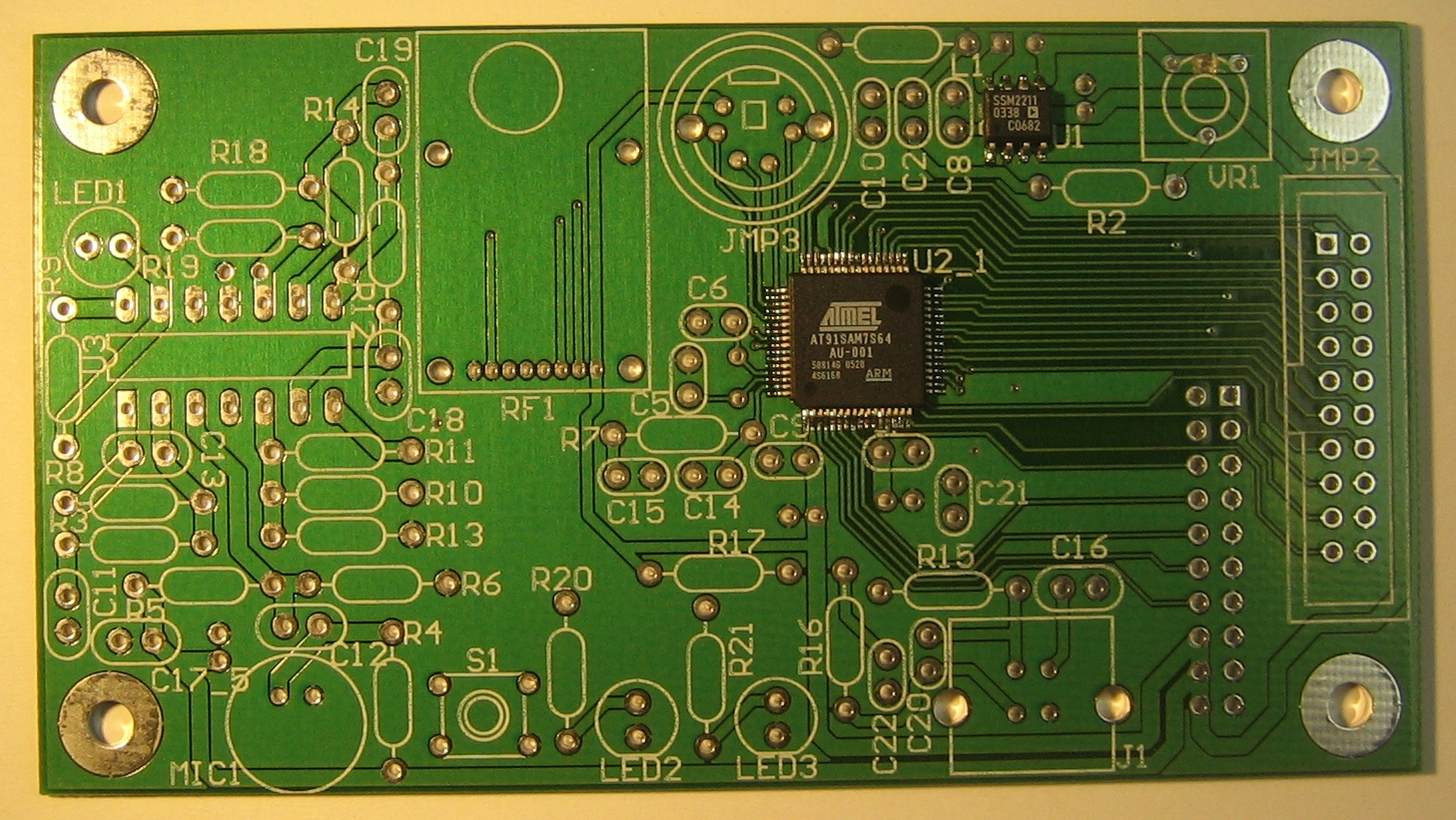
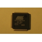
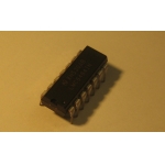
The Atmel ARM7-based AT91SAM7S64 microcontroller. Use a fine-tipped
soldering iron and microscope to solder the microcontroller to the
board. Do a visual and mechanical test of the pins.
|
 |
 |
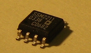
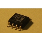
The Analog Devices SSM2211 low distortion 1.5 Watt audio power
amplifier is used with the speaker. Use a fine-tipped soldering iron and
microscope to solder this IC to the board.
|
 |
 |
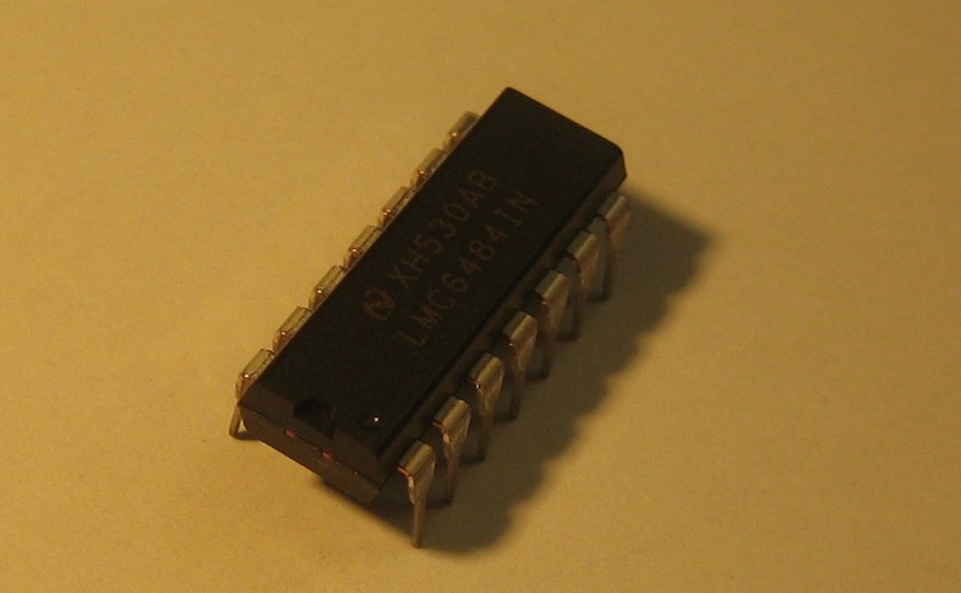
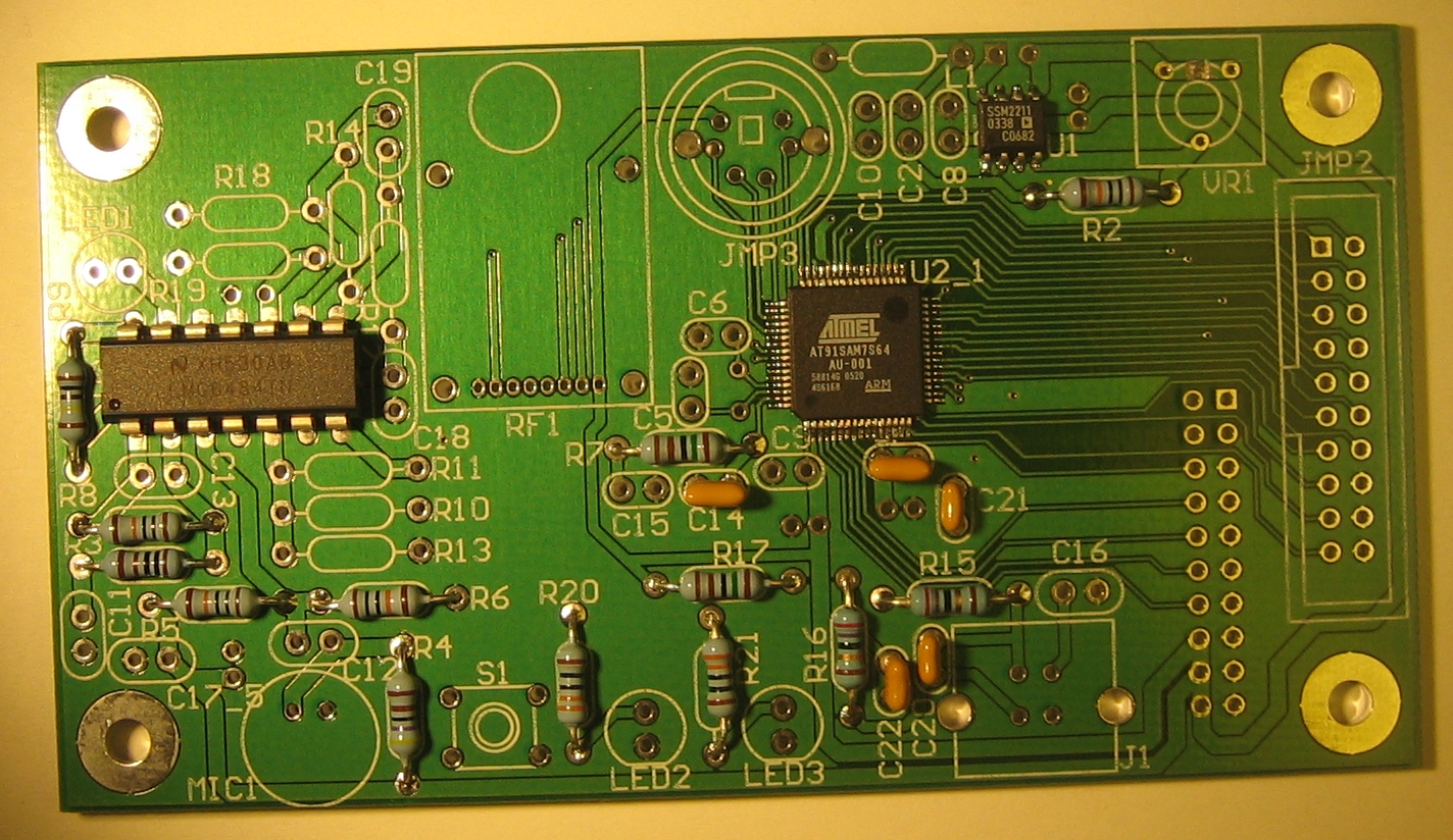
The National Semiconductor LMC6484 CMOS quad rail-to-rail input and
output operational amplifier is used to amplify and/or buffer the
analog sensor signals before they are read by the microcontroller.
|
 |
 |
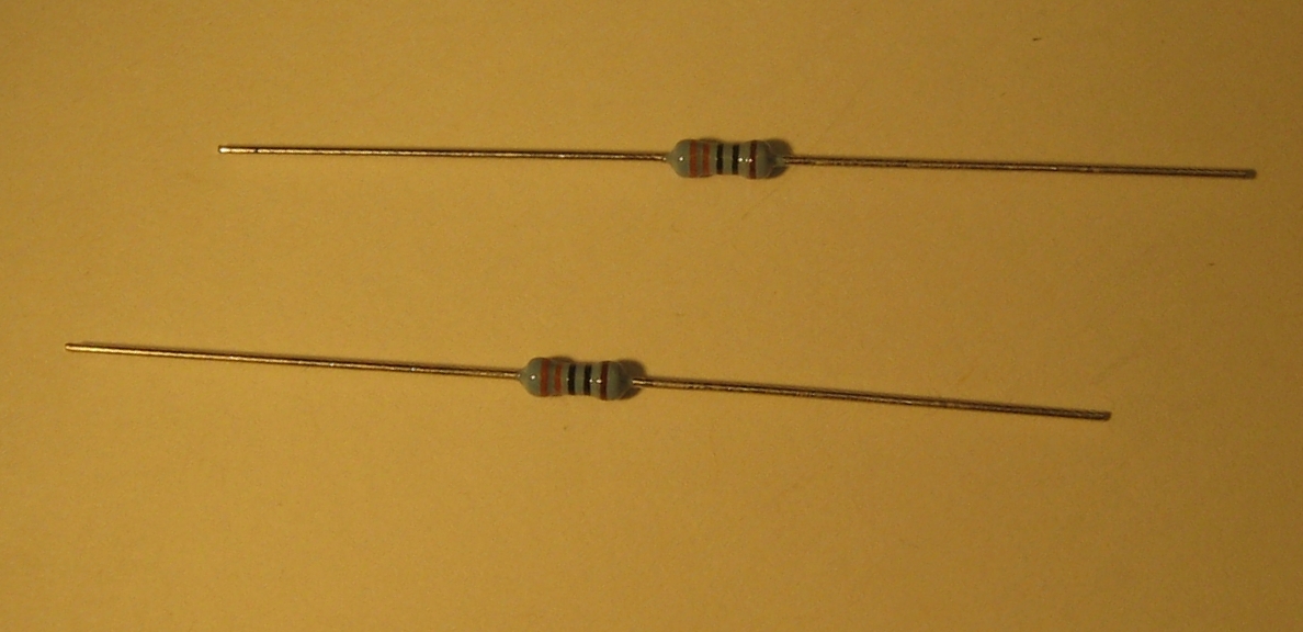
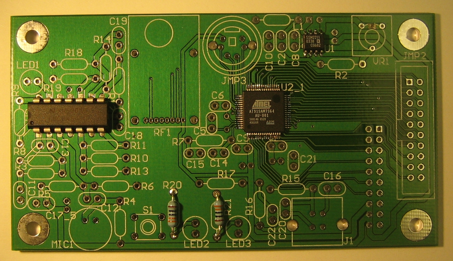
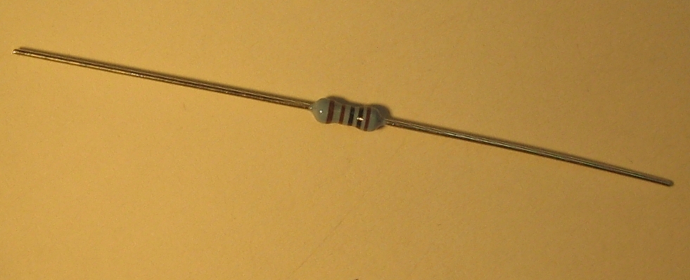
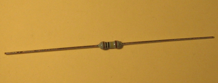
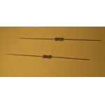
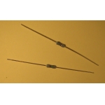
Two 330-Ohm resistors (R20, R21).
|
 |
 |
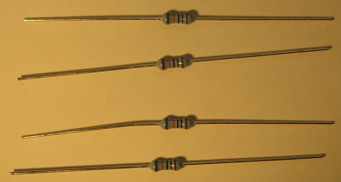
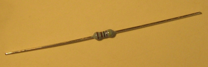
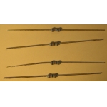
Four 100-kOhm resistors (R2, R5, R6, R8).
|
 |
 |
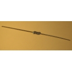
One 1-kOhm resistor (R3).
|
 |
 |
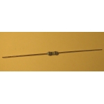
One 4.7-kOhm resistor (R4).
|
 |
 |
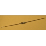
One 1-MOhm resistor (R9).
|
 |
 |
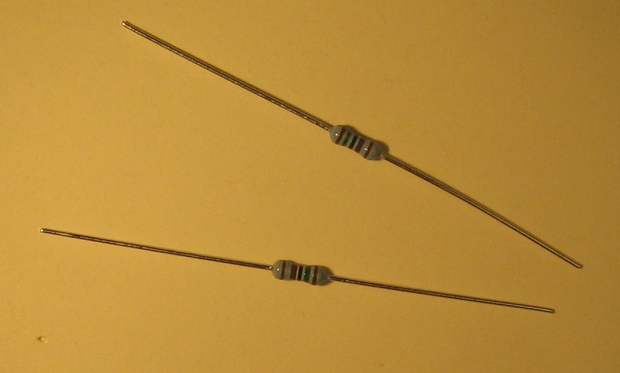
Two 27-ohm resistors (R15, R16).
|
 |
 |
Two 1.5-kOhm resistors (R7, R17).
|
 |
 |
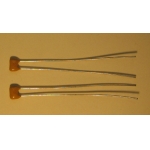
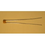
One 33-pF capacitor (C20).
|
 |
 |
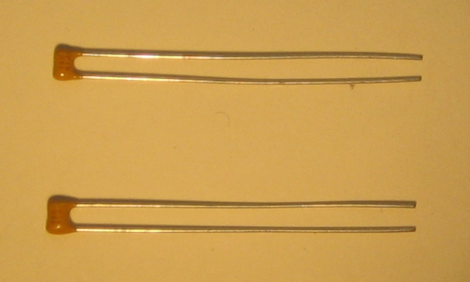
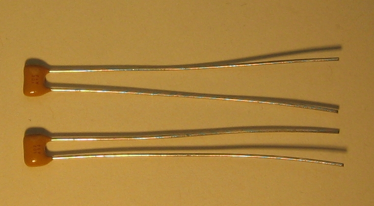
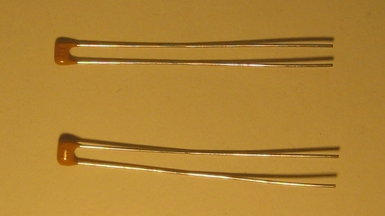
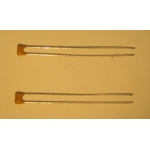
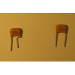
Two 15-pF capacitors (C21, C22).
|
 |
 |
Two 1-nF capacitors (C7, C14).
|
 |
 |
One 10-nF capacitor (C15).
|
 |
 |
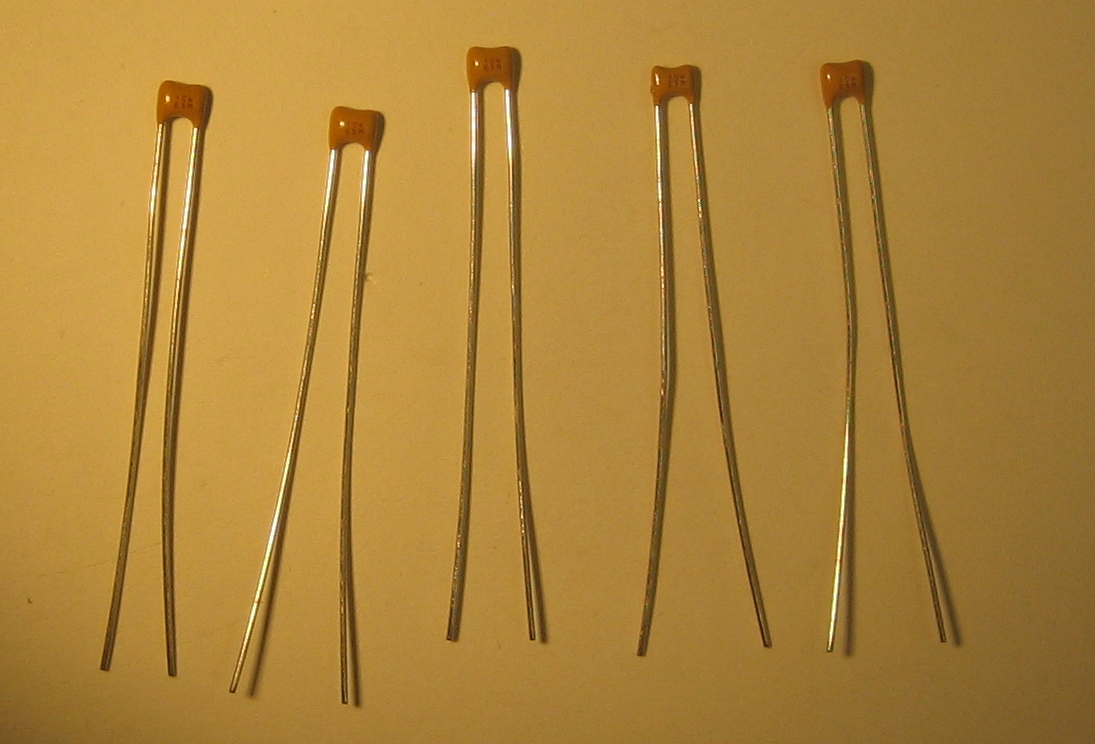
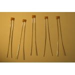
Five 0.1-uF capacitors (C2, C8, C12, C16, C17).
|
 |
 |
Two 10-pF capacitors (C5, C6).
|
 |
 |
One 100-pF capacitor (C13).
|
 |
 |
Two 1-uF capacitors (C9, C10).
|
 |
 |
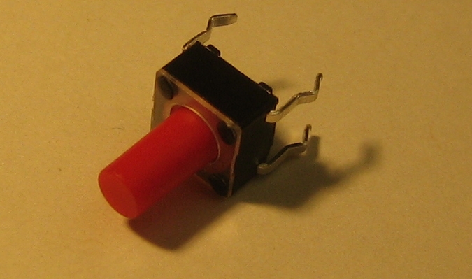
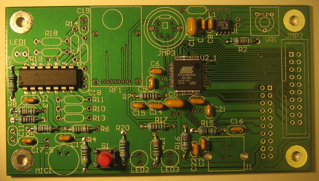
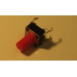
A push-button that can be programmed to perform actions such as
resetting the microcontroller.
|
 |
 |
The JTAG interface for programming and debugging the microcontroller.
|
 |
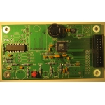 |
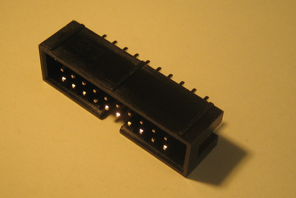
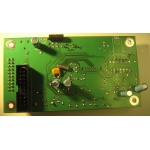
A 20-pin connector for prototyping expansion modules. The notch in
the connector should match the notch in footprint.
|
 |
 |
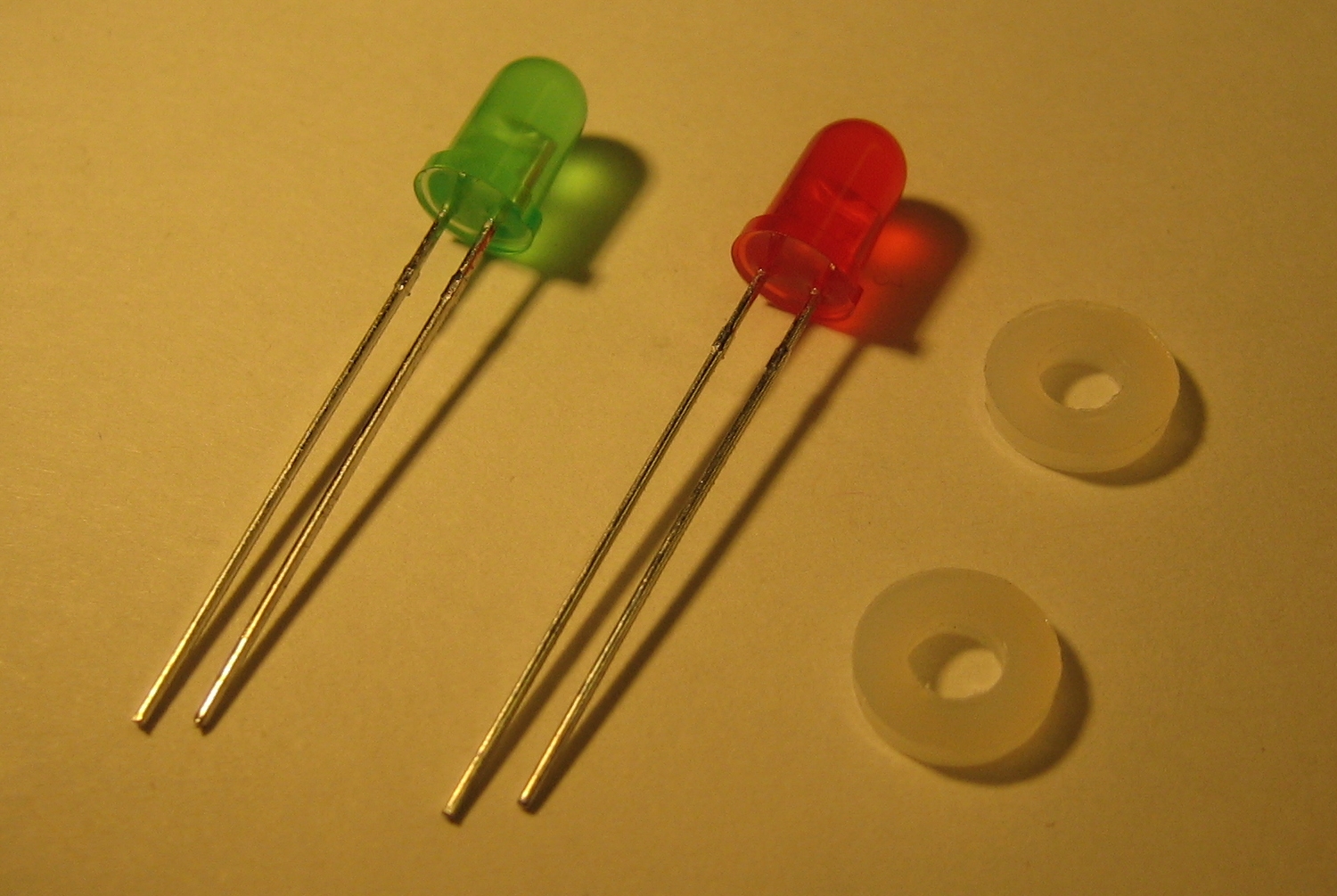
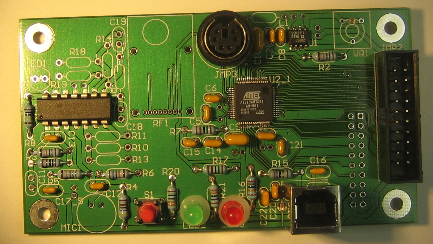
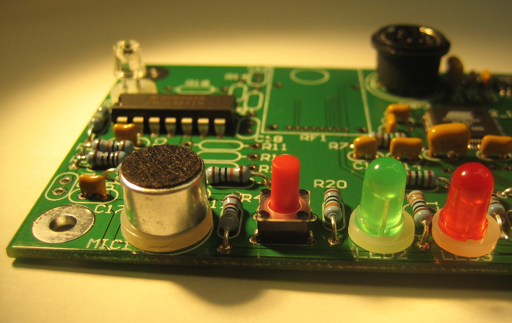
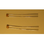
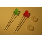
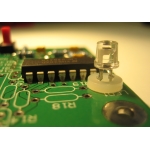
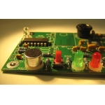
Two LEDs (one green and one red) that can be programmed to display the
status of a program. Be sure the small indentations in each LED align
with the flat portion of the circle indicating the location of the
part on the printed circuit board. For each LED, use one nylon washer
to raise the LED slightly off the board.
|
 |
 |
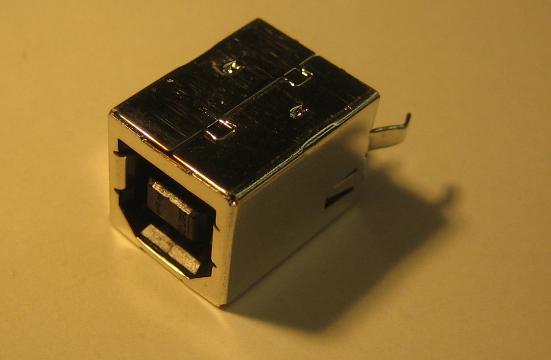
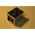
The USB connector for connecting to a PC.
|
 |
 |
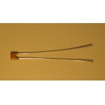
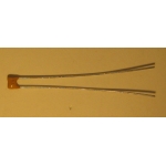
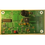
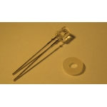
The phototransistor detects light intensity. Use a nylon washer to
hold this part off the board. Note how two small metal tabs on the
leads further hold this part off the washer.
|
 |
 |
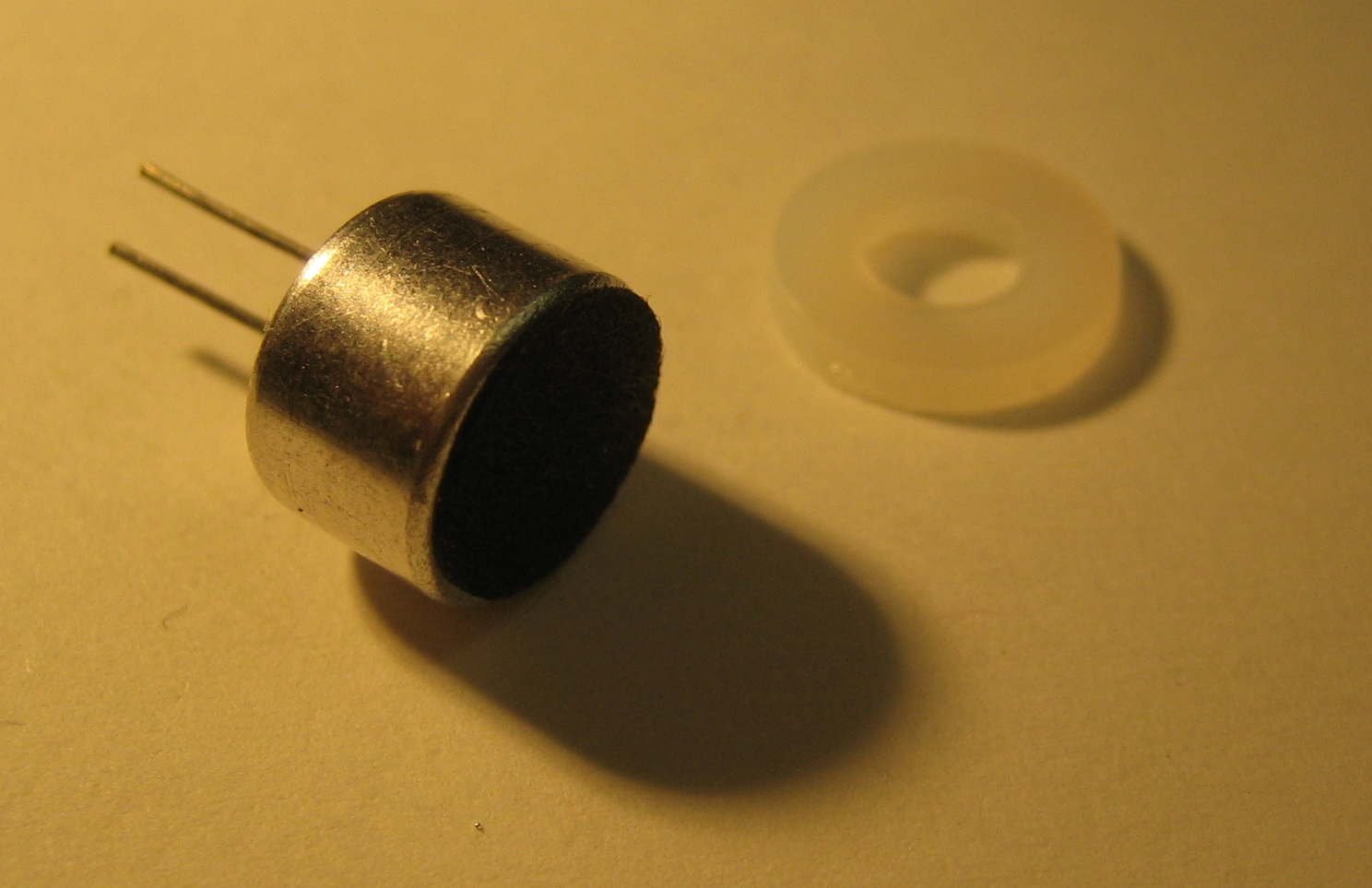
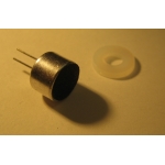
An audio microphone.
|
 |
 |
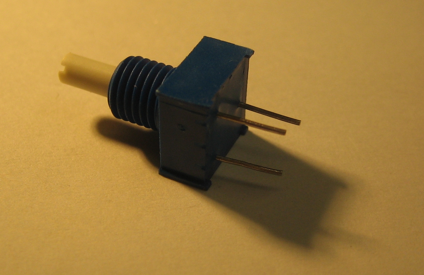
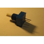
A knob to control the volume of the speaker.
|
|
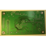 |
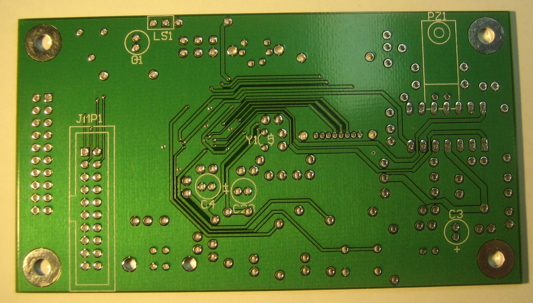
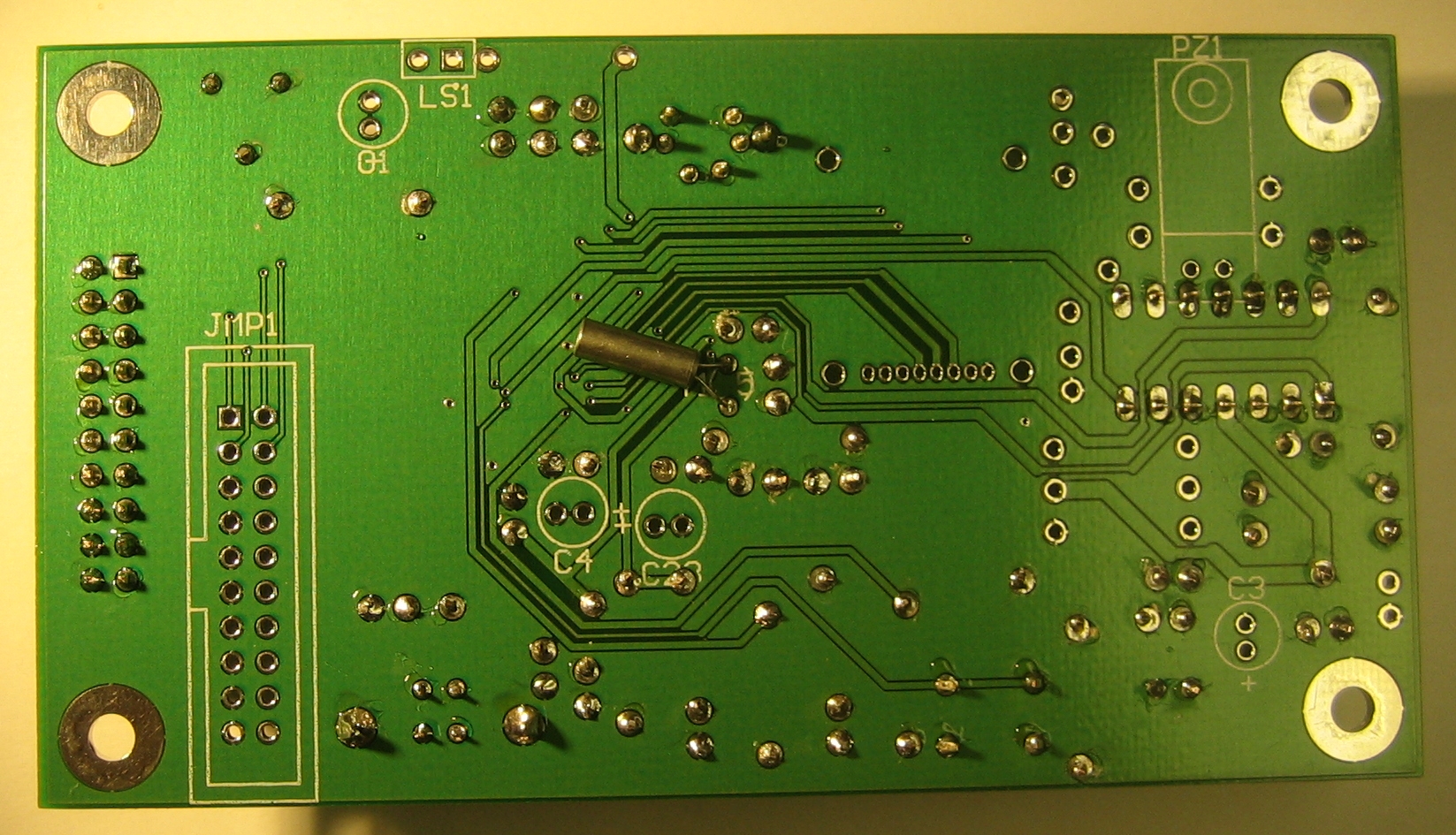
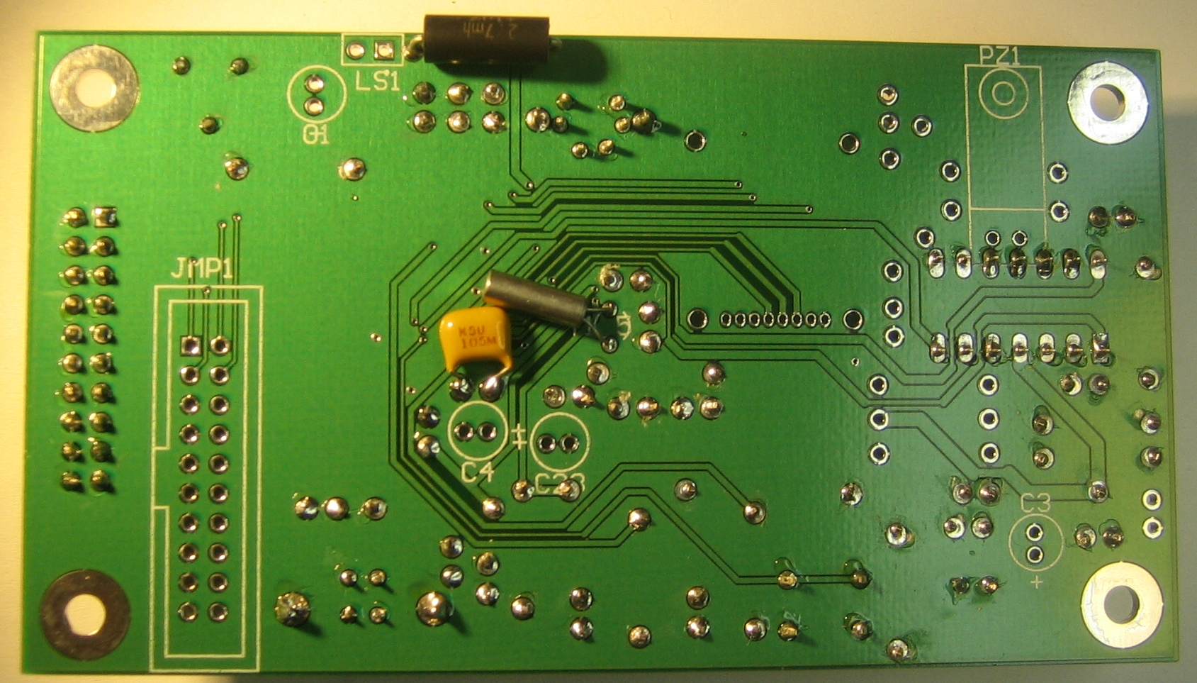
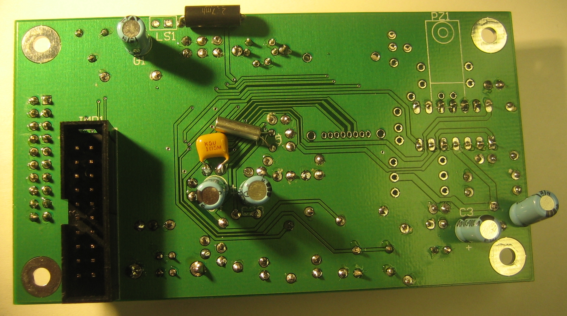
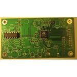
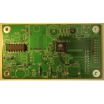
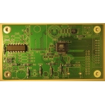
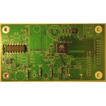
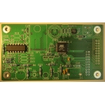
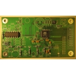
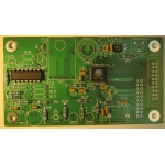
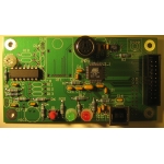
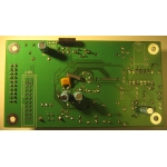
The bottom side of the plug low voltage printed circuit board before any
components have been added.
|
 |
 |
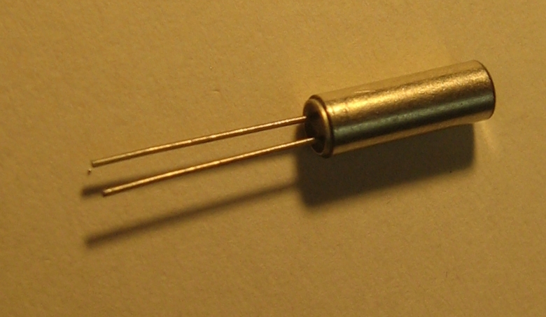
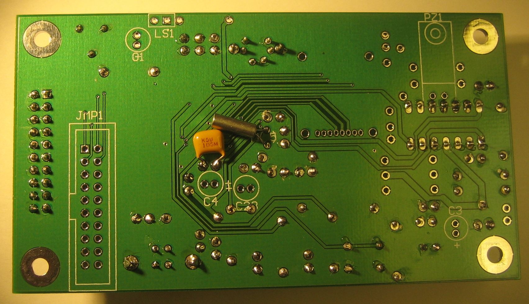
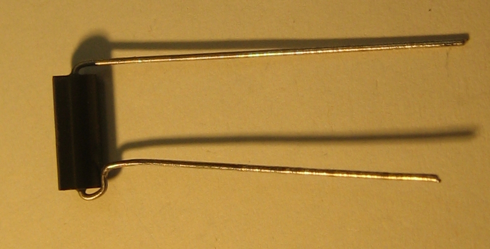
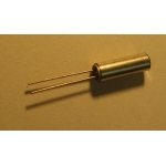
The crystal off of which the microcontroller runs. Clip the excess
leads after soldering to the board.
|
 |
 |
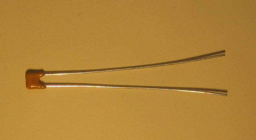
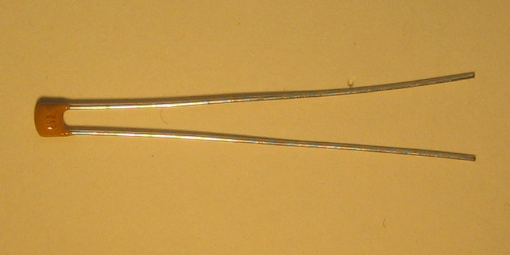
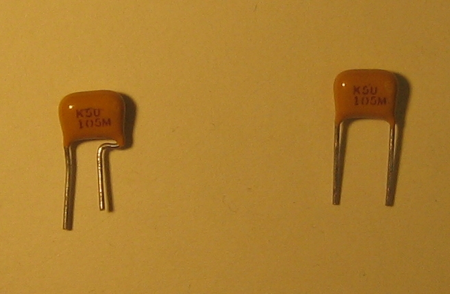
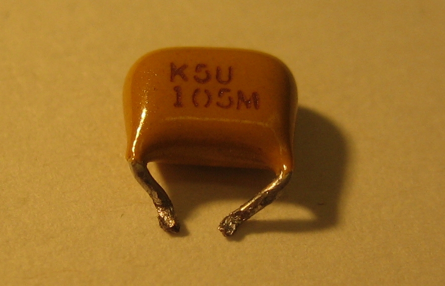
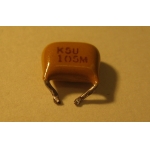
One 1-uF capacitor needs to be added as indicated. This part does not
have an identifier on the board. Clip the leads before soldering to
the board.
|
 |
 |
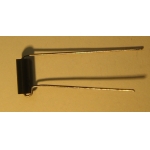
One 2700-uH inductor. Although the footprint is on the top side of
the board, this part should be placed on the bottom of the board as
shown.
|
 |
 |
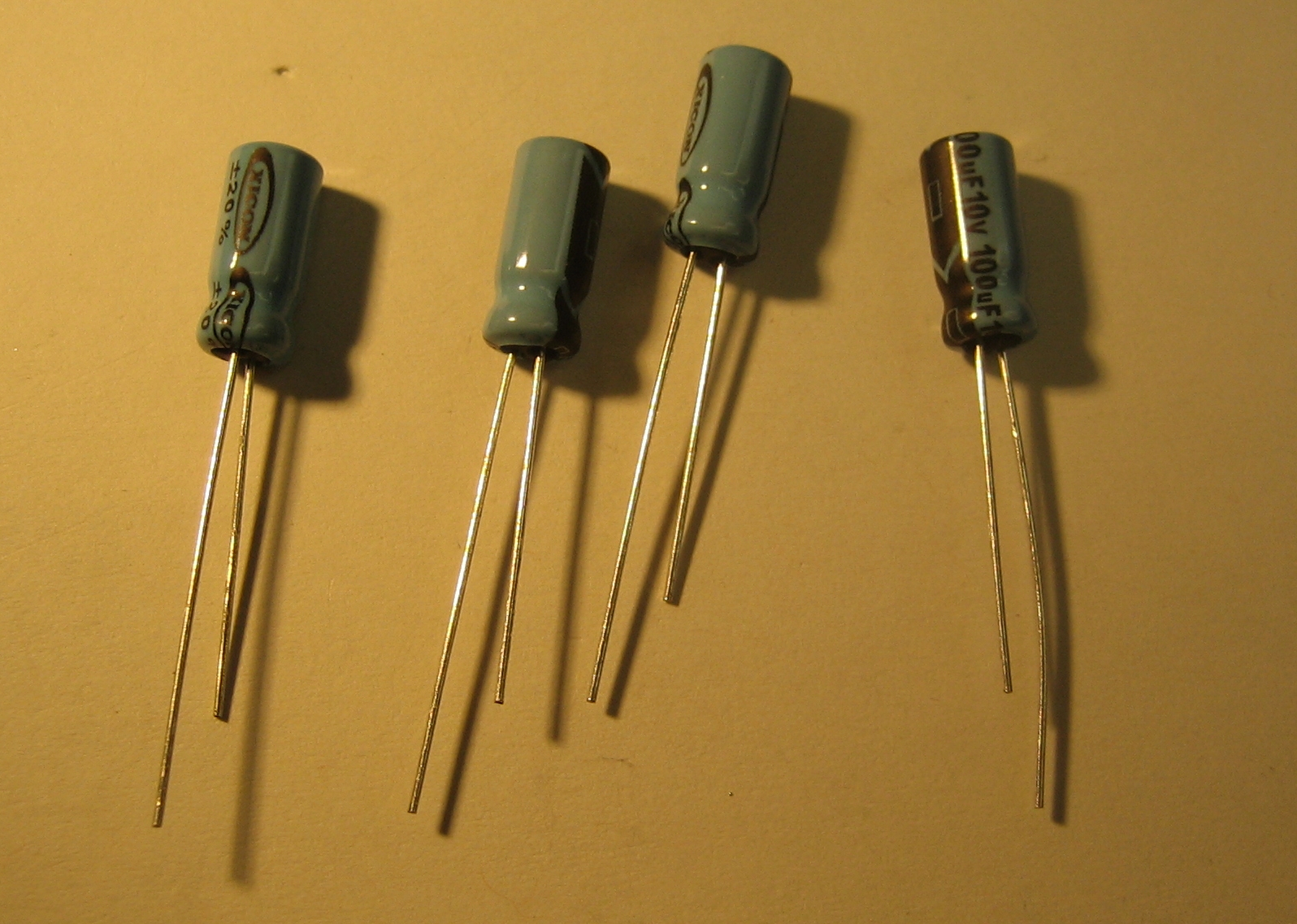
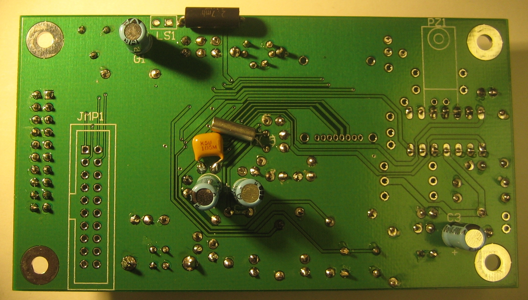
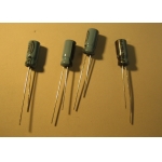
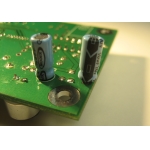
Four 100-uF capacitors (C1, C3, C4, C23). The minus sign side of the part
should go opposite the plus sign side of the part's footprint on the board.
|
 |
 |
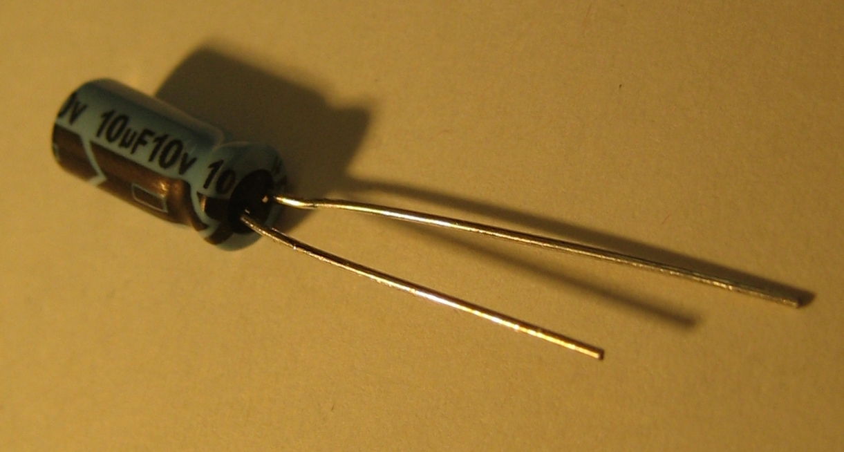
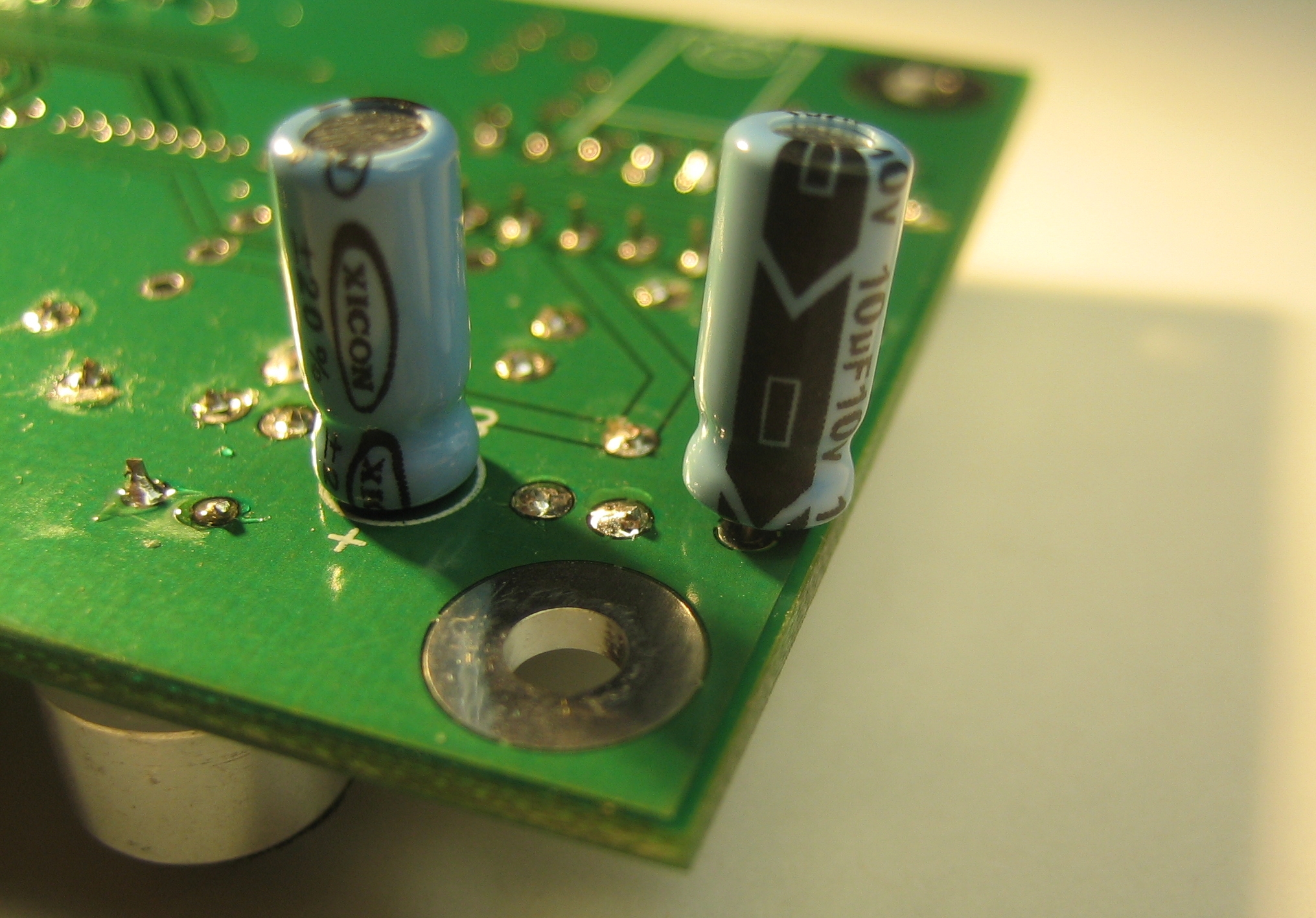
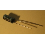
One 10-uF capacitors (C11). Although the part's footprint and
designator (C11) are located on the top side of the board, the part
should be placed on the bottom side as shown. The minus sign side of
the part should be closest to the corner of the board.
|
 |
 |
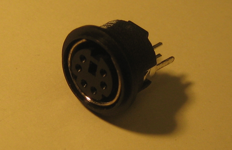
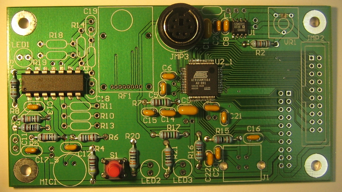
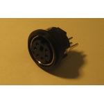
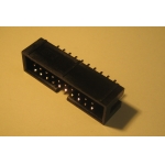
A 20-pin connector for connecting the low voltage board to the high
voltage board. The notch in the connector should match the notch in footprint.
|