The following provides step-by-step instruction for assembling a
complete processing module from its constituent parts.
 |
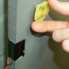
This is the uncut printed circuit board as it comes from the factory. It
consists of four separate boards, one of which is the processing module
board, that must be cut apart and whose edges must be sanded down. A
sheet metal cutter and a grinder work well for these purposes.
|
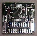 |
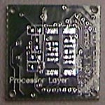
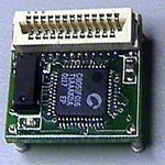
This is the top view of the processing module board after it has been cut
from the original printed circuit board and had its edges sanded, but
before any parts have been added to it. The top
is here defined to be the side on which the expansion connector resides.
It is also the side containing the Cygnal microprocessor.
|
 |
This is the bottom view of the processing module board before any parts
have been added. The bottom is here defined to be the side on which the
communications module connector resides.
|
 |
The microprocessor is the very first part to add to the top of the micro.
This is easily the most difficult and time-consuming step. A separate
tutorial will be posted shortly explaining how to do this.
|
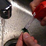 |
If the microprocessor was added to the board with the aid of flux, it is
necessary to remove any remaining flux before adding other parts. This is
because flux is somewhat sticky and particles of metal can easily get
stuck, possibly causing a short between pins. Also, although flux isn't
conductive, it does have a different dielectric constant than air, which
will affect some high-speed applications. Any mild solvent (soap for
example) used under running water with a fine-toothed brush will suffice
to remove excess flux. Brush vigorously. Check the board under a
microscope for spots you may have missed.
|
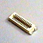 |
The 25-pin receptacle should be soldered to the board after the
microprocessor has been soldered and the board cleaned of excess flux and
dried. The direction the receptacle faces is important, as one side has
12 pins and the other 13 pins. To begin with, solder down a couple of
pins on each side of the receptacle and then check to be sure the
connector is flush with the board. Once it is flush, solder the remaining
pins and the mechanical supports on the two ends. Although the supports do
not make any electrical connections on the receptacle, they are soldered
to ground and power on the board.
|
 |
After soldering on the receptacle, examine the pins under a magnifier
and be sure they do not move when you apply pressure with the tweezers.
Do this now before adding other parts so that you have full access to all
the pins. (The crystal blocks several of the pins otherwise).
|
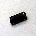 |
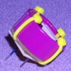
The third part to add to the top of the processing module printed circuit
board is the 22.118MHz crystal. The crystal package has four pins, but
only two of them are electrically active; the other two are provided for
mechanical support. One of the inactive pins must be removed due to the
compactness of the processing layer PCB design. The crystal's footprint
on the PCB reflects this fact. The half-circle notch on one end of the
crystal package should be facing the 25-pin receptacle.
|
 |
Once the crystal has been attached, check for excess solder. The
capacitance of the electrically active pins will effect crystal
performance, so be sure to use only the minimum solder needed for
mechanical support.
|
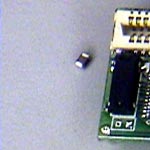 |
Solder on the 4.7uF 0805 footprint capacitor. The polarity
of the capacitor is not important. 0805 designates the physical size of
the capacitor. Unfortunately, there are no markings on the capacitor
itself to indicate that it is 4.7uF (uF is short for microfarad).
|
 |
This is an image of the top of the processing module board after the
4.7uF 0805 footprint capacitor has been added.
|
 |
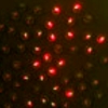
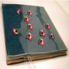
Solder on the red 0603 surface mount red LED. Be sure it is facing the
right way, otherwise it won't work. The very small square embedded in the
LED
should be on the side closest to the microprocessor. Note that if using a
color other than red, the polarity of the LED is most likely reversed.
Presumably, this is an artifact of the manufacturing process used for
this specific brand of LED.
|
 |
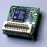
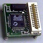
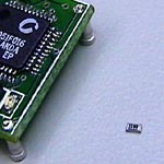
This is an image of the top side of the processing module board with all
its components in place.
|
 |
The four connecting posts protruding from the corners of the bottom side
of the processing module board are retrofitted posts from DIP sockets.
Use wire clippers to cut away the plastic and remove the pins from the DIP
socket.
|
 |
The smaller ends of the posts should be clipped either before or after
being soldered in place. The two posts located under the 25-pin
receptacle should have their smaller ends clipped short before they are
soldered in so as to not be obstructed by the receptacle above. The
length of the clipped pin ends should be only slightly less than the
thickness
of the printed circuit board. These four posts provide mechanical support
and are all electrically active (power, ground, transmit, and receive).
|
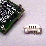 |
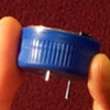
The next part to solder to the bottom of the processing module is the
9-pin receptacle that is used to connect down to a communications
module. The alignment of this part is crucial to how the communication
and processing modules fit together.
|
 |
Once the 9-pin receptacle has been soldered to the board, check all the
connections under a microscope.
|
 |
Select a 0603 footprint 10kOhm resistor. 0603 is the physical size of the
resistor. The resistor's resistance should be printed on the resistor as
a three-digit code. The actual resistance value in Ohms is the number
composed of the two left-most digits times ten raised to the right-most
digit. Thus, 10kOhms is represented by the code 103.
|
 |
Solder on the 10kOhm resistor. This resistor acts as a pull-up resistor
on the active-low reset pin and prevents the microprocessor from
continually resetting itself.
|
 |
Solder on two 18pF capacitors. Due to the cramped board layout, care must
especially be taken here to avoid shorting two separate electrical nets.
As was the case with the 4.7uF capacitor, the polarity of the 18pF
capacitors is not important
|
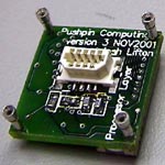 |
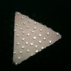
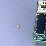
This image shows the completed bottom side of the processing module after
the final part, the 150Ohm (resistor code 151) 0603 footprint resistor,
has been placed.
|
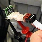 |
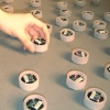
Test the completed Pushpin processing module by downloading a simple
program you know works.
|