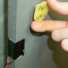
Time of Flight Expansion Module
 |
Sensing |
| • Phototransistor |
|
| • 40KHz Sonar Transducer |
|
| • Electret Micrphone | |
| Actuation | |
| • RGB LED | |
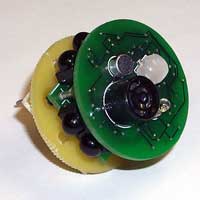
Description
The Time of Flight (TOF) expansion module is specifically designed to aid in Pushpin localization research by measuring the time difference of arrival between a flash of light and a sonar pulse. To this end, the TOF module has a phototransistor for detecting light and a sonar transducer for detecting 40KHz ultrasound signals.
The raw signal from the phototransistor is fed directly into an A/D input on the Pushpin processing module for normal light sensing, but this signal is also fed into conditioning circutry that detecting fast light transients (as from the camera flash on the Pinger device). This flash detector circuitry triggers a hardware interrupt on the processing layer, thereby freeing the processor from the task of constantly monitoring the phototransister input while waiting for a flash of light to occur. The sonar transducer also generates a hardware interrupt whenever sonar stimulus is present.
An electret microphone is also included for detecting audio signals in future sensing applications. The signal from the microphone can read by the A/D in the processing layer in its raw form. However, the signal processing capabilities of the 8-bit microcontroller at the heart of the processing layer are limited due to its lack of memory or dedicated hardware for precise arithmetic (e.g. no floating point unit or hardware multiply instructions). It is often saves valuable processor time, therefore, to take the low pass filtered version of the microphone signal from the dedicated envelope follower circuit included on the TOF expansion module board.
For actuation, the TOF module features a tri-color (red, green, blue) LED that allows the Pushpin to visually indicate its current state. The LED can also be used as a display element when a Pushpin node participates as a "smart pixel" in a distributed display task.
Schematic Diagram
[PDF]
Printed Circuit Board Layout
[PDF]
|
|
|
|
|
|
|
|