
People Publications Introduction Inspiration Software Hardware See the nodes in Action!
SOFTWARE SIMULATION
The design of the software simulator can be broken down into 3 sections:
1) ENVIRONMENTAL SIMULATION
The first step in setting up a simulation is to layout the environment using the Parasitic Mobility Simulator Map Editor. The user interface for this tool consists of a window displaying a scrollable, tile-based map, and a control panel for editing the parameters of the selected tile. Once a map is created, it can then be imported into the Parasitic Mobility Simulator, where a user can set up behaviors for the hosts and paramors, set up logging, and begin execution of the simulation.
Below
(left): Parasitic Mobility Simulator Map Editor
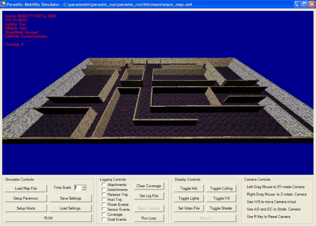
Below (right): The Parasitic Mobility Simulator executing a simulation.
2) HOST BEHAVIOR
The simulation allows the user to assign several parameters to the hosts. These parameters include: stay weight; covered/uncovered weights; portal weight; portal duration; and speed.
3) PARASITIC NODE BEHAVIOR
Similarly, properties can be assigned to the node’s behavior. These properties include: power rate; attachment power; battery life; power threshold; goal x/y coordinates; “goto goal;” “stop at goal;” goal time; light/vibration/altitude/temperature/radiation threshold’ sensor time; coverage; and hops per locale.