HARDWARE SYSTEM
To test the concept of parasitic mobility in a real world setting, a hardware system comprised of electronic nodes with all the necessary elements was designed and built. The nodes required processing, communication, data storage, a location system, a suite of sensors, and an onboard rechargeable power source.
Pictures
(top-bottom):
1)
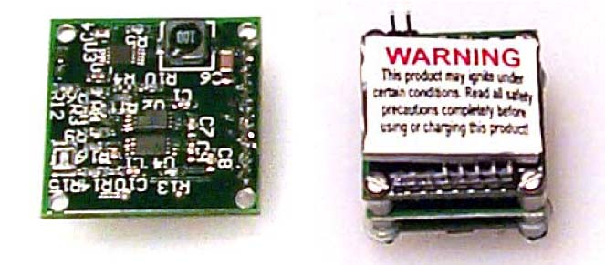
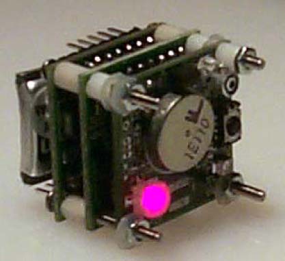
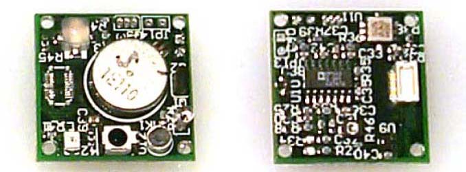
Node Hardware with 3 layers (approx. 1 square inch)
2) The power module is based around a Lithium Polymer rechargeable battery. It contains the battery, the ability to switch off in the presence of an external power source, a highly efficient step-down converter, and a gas gauge chip to monitor battery usage.
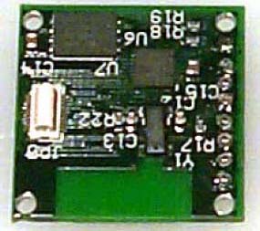
3) The processing and communication module consists of a Silicon Labs C8051F311 microcontroller and a BR-C11A Class 1 Bluetooth module from BlueRadios, Inc. Each node is equipped with a wireless communication system to allow nodes to communicate with each other.
4) The sensor and actuation module contains the following: 2 axis accelerometer, microphone, active infrared proximity sensor, temperature sensor, light sensor, RGB LED, pager motor, and motor controller.
5)
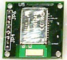
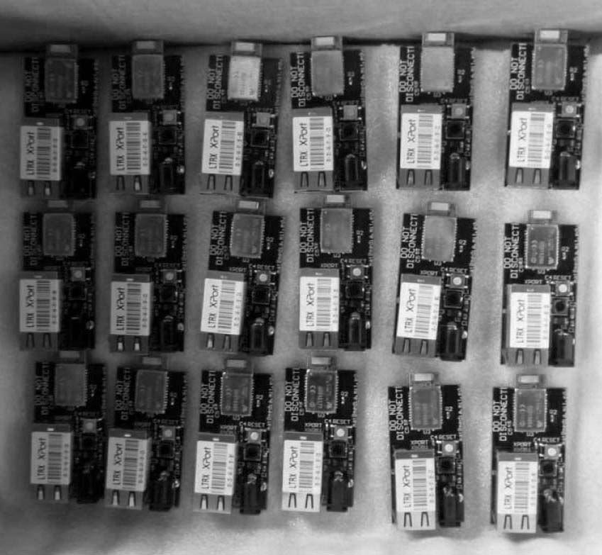
The location and monitoring system consists of 2 different designs.
The first is a GPS Module based around the Motorola FS OnCOre single chip
GPS module. The second system is a series of Bluetooth beacons, each with
a 10 meter range, placed in an overlapping grid around the area of interest.
The image shows Bluetooth location beacons rady to be deployed.